Universal Asynchronous Receive Transmit (UART)
Introduction
The UART supports synchronous one-way communication, half-duplex single wire communication, and multiprocessor communications(CTS/RTS).
Features
- Serial-to-parallel conversion on data received from a peripheral device
- Parallel-to-serial conversion on data transmitted to the peripheral device
- Data size of 5,6,7 and 8 its
- One or two stop bits
- Even, odd, stick, or no-parity bit generation and detection
- Support of hardware flow control
- Programmable FIFO disabling for 1-byte depth.
- Programmable use of UART or IrDA SIR input/output
- False start bit detection
Functional description
UART bidirectional communication requires a minimum of two pins: RX, TX The frame are comprised of:
- An Idle Line prior to transmission or reception
- A start bit
- A data word (8 or 9 bits) least significant bit first
- 1, 1.5, 2 Stop bits indicating that the frame is complete
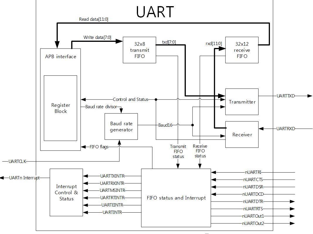
- The USART interface uses a baud rate generator
- A status register (UART1_RISR)
- data registers (UART1DR)
- A baud rate register (UART1_IBRD,UART1_FBRD)
The below figure shows UART0,1 Block diagram
The below Figure shows the UART character frame

Baud rate calculation
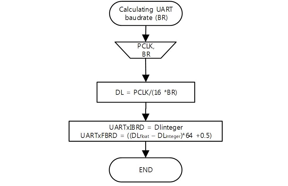
UARTx can operate with or without using the Fractional Divider. The baud rate divisor is a 22-bit number consisting the UARTxIBRD(16-bit integer) and the UARTxFBRD(6-bit fractional). This is used by the baud rate generator to determine the bit period.
The below Figure shows UART divider flow chart
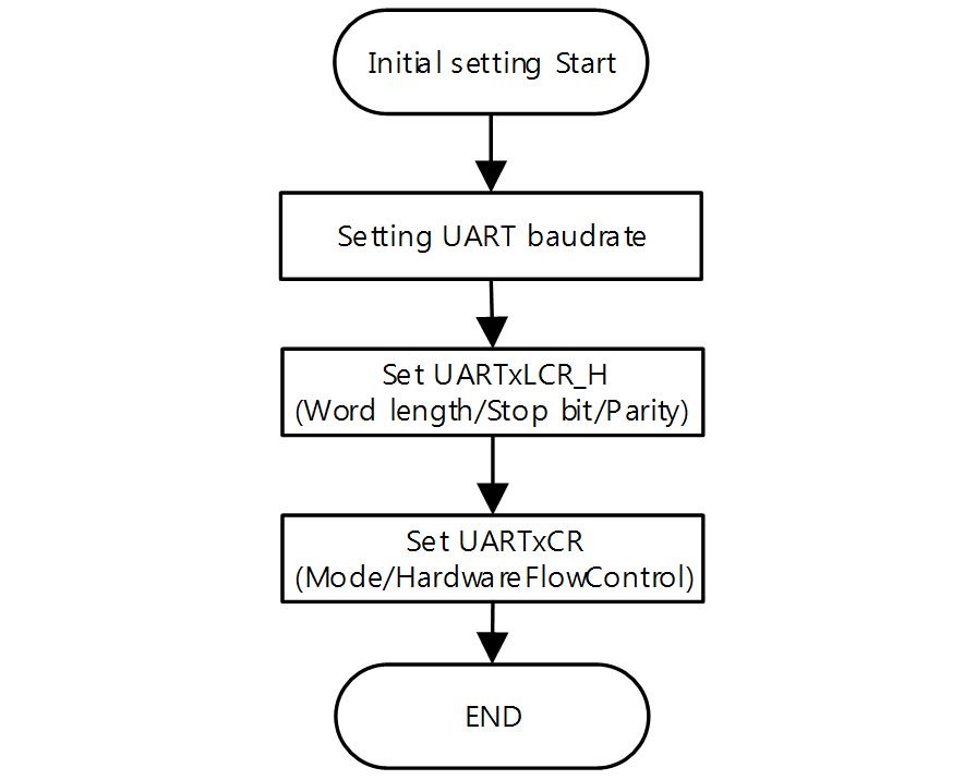
The below Figure shows how to set the UART Initial value.
Data transmission
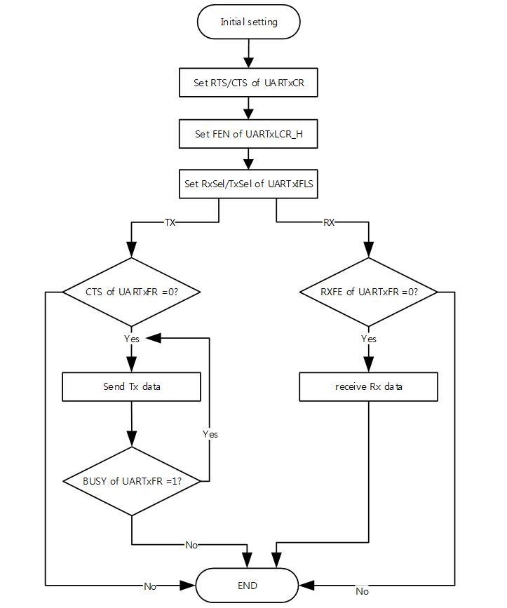
Data transmitted is stored in a 32-byte FIFOs. Transmit data is written into the transmit FIFO for transmission. If UART is enabled, it causes a data frame to start transmitting with parameters indicated in the UARTxLCR_H. Data continues to transmit until there is no data left in the transmit FIFO. The BUSY bit of UARTxFR is ‘1’ as soon as data is written to the transmit FIFO, which means the FIFO is not empty, and remains as ‘1’ while data is being transmitted.
Data receive
Received data is stored in the 32-byte FIFOs. When a start bit has been received, it begins running and data is sampled on the eighth cycle of that counter in UART mode. A valid stop bit is confirmed if UARTRXD is ‘1’. When a full word is received, the data is stored in the receive FIFO. Error bit is stored in bit[10:8] of UARTxCR and overrun is stored in bit[11] of UARTxCR.
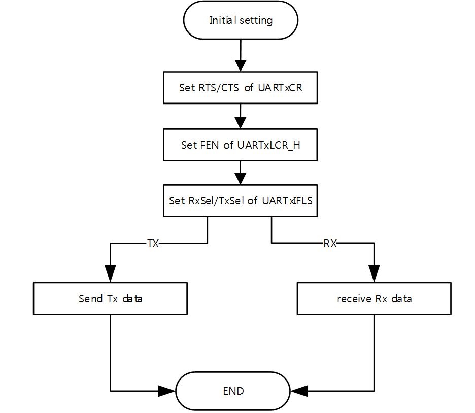
The below figure shows Transmit and Receive data flow chart.
Hardware flow control
The below Figure shows Hardware flow control description.
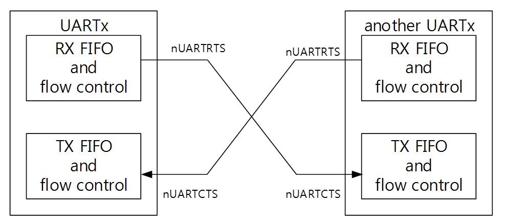
The RTS flow control is enabled by setting the RTSen of UARTxCR. If RTS is enabled, the data flow is controlled as follows. When the receiver FIFO level reaches the programmed trigger level, nUARTRTS(pin) is asserted(to a low value). nUARTRTS is reasserted(to a low level) once the receiver FIFO has reached the previous trigger level. The reasserted of nUARTRTS signals to the sending UART to continue transmitting data.
The CTS flow control is enabled, the transmitter can only transmit data when nUARTCTS is asserted. When nUARTCTR is re-asserted(to a low) the transmitter sends the next byte. To stop the transmitter from sending the following byte, nUARTCTS must be released before the middle of the last stop bit that is currently being sent.
The below Figure shows CTS Functinoal Timing.

The below Figure shows how software should use the RTS/CTR.
