Direct Memory Access (DMA)
Introduction
Direct memory access (DMA) is used in order to provide high-speed data transfer between peripherals and memory as well as memory to memory. Data can be quickly moved by DMA without any CPU actions. This keeps CPU resources free for other operations.
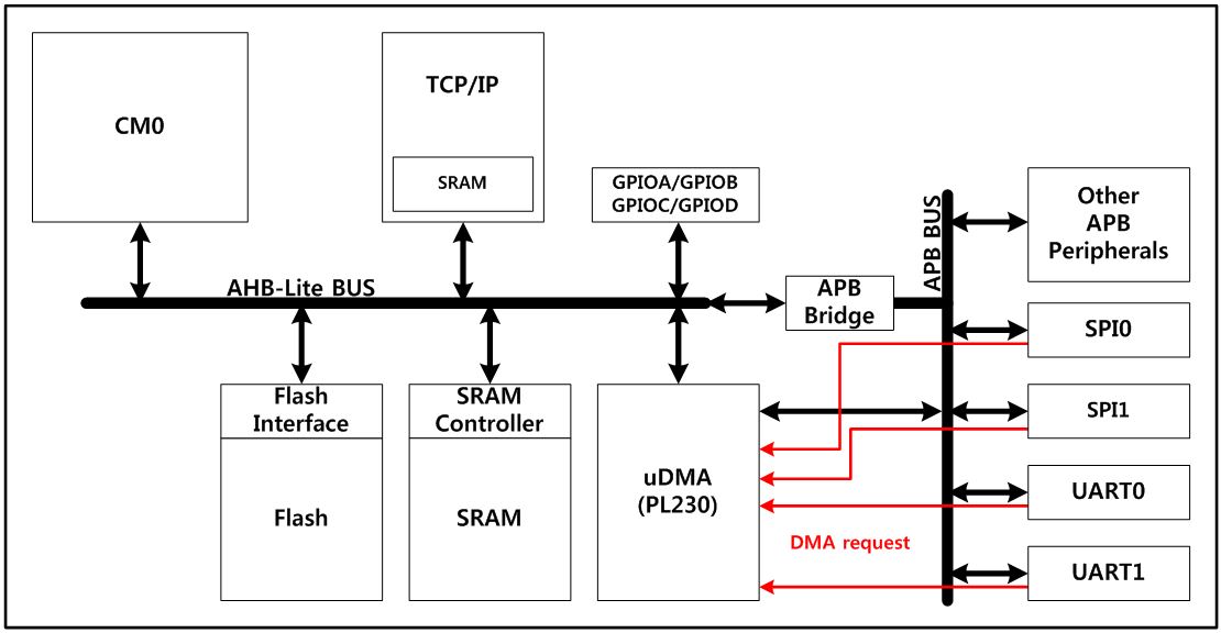
The DMA controller has up to 6 channels in total, each dedicated to managing memory access requests from one or more peripherals. It has an arbiter for handling the priority between DMA requests. For more details, refer to “PrimeCell® μDMA Controller (PL230)” from the Technical Reference Manual
Features
- 6 channels
- Each channel is connected to dedicated hardware DMA requests and software trigger is also supported on each channel.
- Priorities between requests from the DMA channels are software programmable (2 levels consisting of high, default)
- Memory-to-memory transfer (software request only)
- TCP/IP-to-memory transfer (software request only)
- Access to Flash, SRAM, APB and AHB peripherals as source and destination
Functional description

DMA request mapping
The hardware requests from the peripherals (UART0, UART1, SSP0, SSP1) are simply connected to the DMA. Refer to the below Table Summary of the DMA requests for each channel which lists the DMA requests for each channel.
| Channel 1 | Channel 2 | Channel 3 | Channel 4 | Channel 5 | Channel 6 | |
|---|---|---|---|---|---|---|
| Hardware request | SSP0_TX SSP0_RX | SSP1_TX SSP1_RX | UART0_TX UART0_RX | UART1_TX UART1_RX | Channel 5 | Channel 6 |
| Software request | Support | Support | Support | Support | Support | Support |
- Software request is only way to use DMA for memory-to-memory or TCP/IP-to-memory.
DMA arbitration
The controller can be configured to perform arbitration during a DMA cycle before and after a programmable number of transfers. This reduces the latency for servicing a higher priority channel. The controller uses four bits in the channel control data structure that configures how many AHB bus transfers occur before the controller re-arbitrates. These bits are known as the R_power bits because the value R is raised to the power of two and this determines the arbitration rate. For example, if R = 4, then the arbitration rate is 2^4, which means the controller arbitrates every 16 DMA transfers.
Remark: Do not assign a low-priority channel with a large R_power value because this prevents the controller from servicing high-priority requests until it re-arbitrates.
When N > 2R and is not an integer multiple of 2R then the controller always performs sequences of 2R transfers until N < 2R remain to be transferred. The controller performs the remaining N transfers at the end of the DMA cycle.
DMA cycle types
The cycle_ctrl bits in the channel control data structure contril how the DMA controller performs a cycle.
The controller uses four cycle types described in this manual:
- Invalid
- Basic
- Auto-request
- Ping-pong
See ARM micro DMA (PL230) documentation for additional cycle types.
For all cycle types, the controller arbitrates after 2R DMA transfers. If a low-priority channel is set to a large 2R value then it prevents all other channels from performing a DMA transfer until the low-priority DMA transfer completes. Therefore, the user must be cautious when setting the R_power bit in the channel_cfg data structure so that the latency for high-priority channels is not significantly increased.
Invalid cycle
After the controller completes a DMA cycle, it sets the cycle type to invalid to prevent it from repeating the same DMA cycle.
Basic cycle
In this mode, the controller can be configured to use either the primary or the alternate channel control data structure. After the channel is enabled and the controller receives a request for this channel, the flow for basic cycle is as below:
- The controller performs 2R transfers. If the number of transfers remaining is zero the flow continues at step 3.
- The controller arbitrates:
- If a higher-priority channel is requesting service, then the controller services that channel.
- If the peripheral or software signals a request to the controller, then it continues at step 1.
- The controller sets dma_done[c] signal for this channel HIGH for one system clock cycle. This indicates to the host processor that the DMA cycle is complete.
Auto request cycle
When the controller operates in this mode, it is only necessary to receive a single request to enable the controller to complete the entire DMA cycle. This enables a large data transfer to occur, without significantly increasing the latency for servicing higher priority requests or requiring multiple requests from the processor or peripheral.
The auto-request cycle is typically used for memory-to-memory requests. In this case, software generates the starting request for the 2^R transfers after setting up the DMA control data structure.
In this mode, the controller can be configured to use either the primary or the alternate channel control data structure. After the channel is enabled and the controller receives a request for this channel, the flow for the auto-request cycle is as below:
- The controller performs 2R transfers. If the number of transfers remaining is zero the flow continues at step 3.
- The controller arbitrates if there are any transfers remaining after 2R transfers. If the current channel c has the highest priority, the cycle continues at step 1.
- The controller sets dma_done[c] signal for this channel HIGH for one system clock cycle. This indicates to the host processor that the DMA cycle is complete.
Pingpong cycle
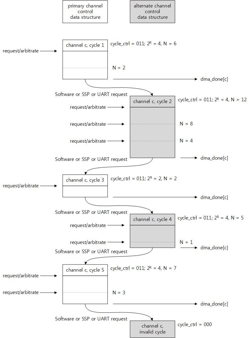
In this mode, the controller performs a DMA cycle using one of the data structures and then performs a DMA cycle using the other data structure. The controller continues to switch between primary and alternate structures until it either reads a data structure that is invalid, or until the user reprograms the cycle_type to basic, or until the host processor disables the channel.
In ping-pong mode, the user can program or reprogram one of the two channel data structures (primary or alternate) while using the other channel data structure for the active transfer. When a transfer is done, the next transfer can be started immediately using the prepared channel data structure – provided that a higher priority channel does not require servicing. If the user does not reprogram the channel control data structure not in use for a transfer, the cycle type remains invalid (which is the value at the end of the last transfer using that structure) and the ping-pong cycle completes.
The ping-pong cycle can be used for transfers to or from peripherals or for memory-to-memory transfers.
