W55RP20-EVB-PICO
Overview
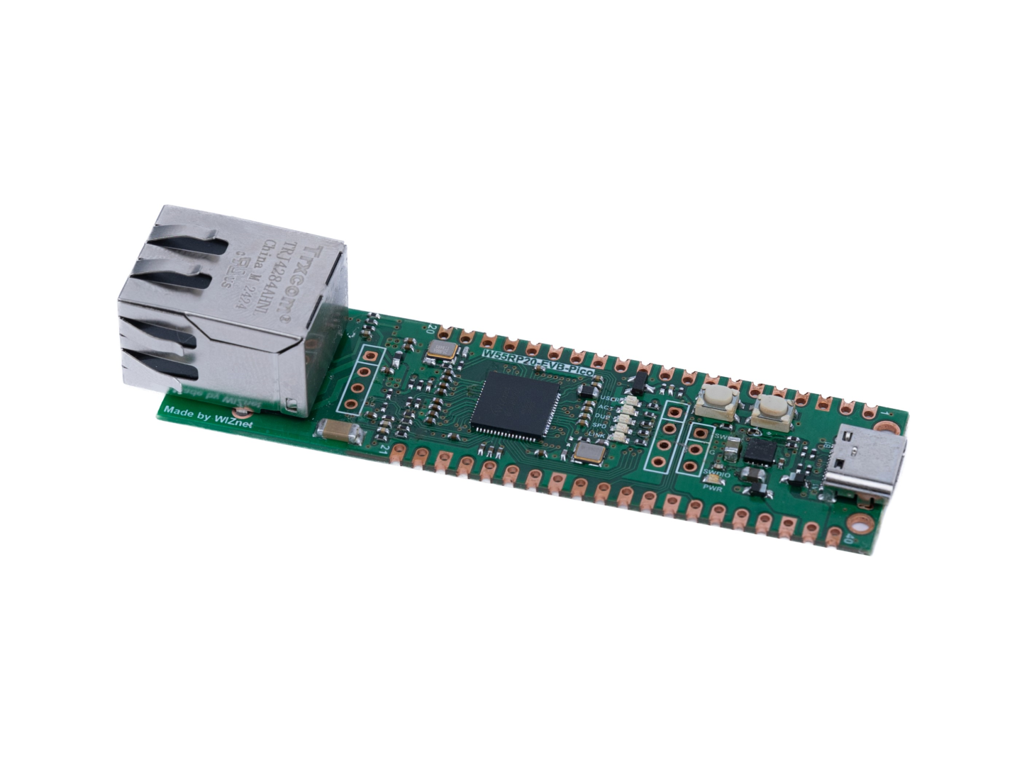
W55RP20-EVB-Pico is an evaluation board for W55RP20, a chip that combines W5500, a wired TCP/IP controller, and RP2040. Therefore, both the functions of Raspberry Pi Pico and those of the W5500 are available.
- Raspberry Pi Pico Clone
- Ethernet (W55RP20 Hardwired TCP/IP CHIP)
- AWS IoT Core Qualified

Features
- W55RP20 microcontroller
- Internal 2MByte Flash
- Dual-core cortex M0+ at up to 133MHz
- 264kByte multi-bank high performance SRAM
- External Quad-SPI Flash with eXecute In Place (XIP)
- High performance full-crossbar bus fabric
- 22 multi-function General Purpose IO (4 can be used for ADC)
- 1.8-3.3V IO Voltage (NOTE. Pico IO voltage is fixed at 3.3V)
- 12-bit 500ksps Analogue to Digital Converter (ADC)
- Various digital peripherals
- 2 × UART, 2 × I2C, 2 × I2C, 2 × SPI, 16 × PWM channels
- 1 × Timer with 4 alarms, 1 × Real Time Counter
- 2 × Programmable IO (PIO) blocks, 8 state machines total
- Flexible, user-programmable high-speed IO
- Can emulate interfaces such as SD Card and VGA
- Supports Hardwired Internet Protocols: TCP, UDP, ICMP, IPv4, ARP, IGMP, PPPoE
- Supports 8 Independent Hardware SOCKETs simultaneously
- Internal 32 Kbytes Memory for TX/ RX Buffers
- Supports High Speed Serial Peripheral Interface(SPI MODE 0, 3)
- USB C port for power and data (and for reprogramming the Flash)
- 3-pin ARM Serial Wire Debug (SWD) port
- 10 / 100 Ethernet PHY embedded
- Supports Auto Negotiation
- Full / Half Duplex
- 10 / 100 Based
- Built-in RJ45 (POE)
- Built-in DCDC (PWM/PFM)
- Additional modules are installed to enable POE
Hardware Specification
Pin-out
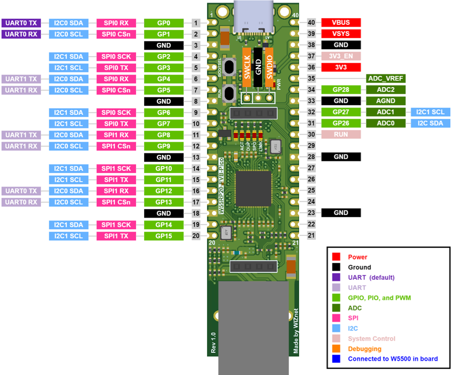
W55RP20-EVB-Pico pinout is directly connected to the GPIO of RP2040 as shown in the above picture. It has the same pinout as the Raspberry Pi Pico board. However, GPIO17, GPIO20, GPIO21, GPIO22, GPIO23, GPIO24, and GPIO25 are not available due to the connection inside the board.
The W55RP20 GPIO used inside W55RP20-EVB-Pico is as follows.
| I/O | Pin Name | Description |
|---|---|---|
| O | GPIO16 | DCDC Mode Select Pin |
| I | GPIO18 | VBUS sense - high if VBUS is present, else low |
| O | GPIO19 | Connected to user LED |
| I | GPIO29 | Used in ADC mode (ADC3) to measure VSYS/3 |
Apart from GPIO and ground pins, there are 7 other pins on the main 40-pin interface:
| Pin No. | Pin Name | Description |
|---|---|---|
| PIN40 | VBUS | Micro-USB input voltage, connected to micro-USB port pin 1. Nominally 5V. |
| PIN39 | VSYS | Main system input voltage, which can vary in the allowed range 4.3V to 5.5V, and is used by the on-board LDO to generate the 3.3V . |
| PIN37 | 3V3_EN | Connects to the on-board LDO enable pin. To disable the 3.3V (which also de-powers the RP2040 and W5500), short this pin low. |
| PIN36 | 3V3 | Main 3.3V supply to RP2040 and W5500, generated by the on-board LDO. |
| PIN35 | ADC_VREF | ADC power supply (and reference) voltage, and is generated on W5500-EVB-Pico by filtering the 3.3V supply. |
| PIN33 | AGND | Ground reference for GPIO26-29. |
| PIN30 | RUN | RP2040 enable pin, To reset RP2040, short this pin low. |
Operation Condition
| Item | Description |
|---|---|
| Operation Temperature MAX | 85C (including self-heating) |
| Operation Temperature MIN | -45C |
| VBUS | DC 5V (+/- 10%) |
| VSYS Min | DC 4.3V |
| VSYS Max | DC 5.5V |
Recommended maximum ambient temperature of operation is 70C.
Technical Reference
RP2040 Datasheet
W5500 Datasheet
W55RP20 Datasheet
Schematic
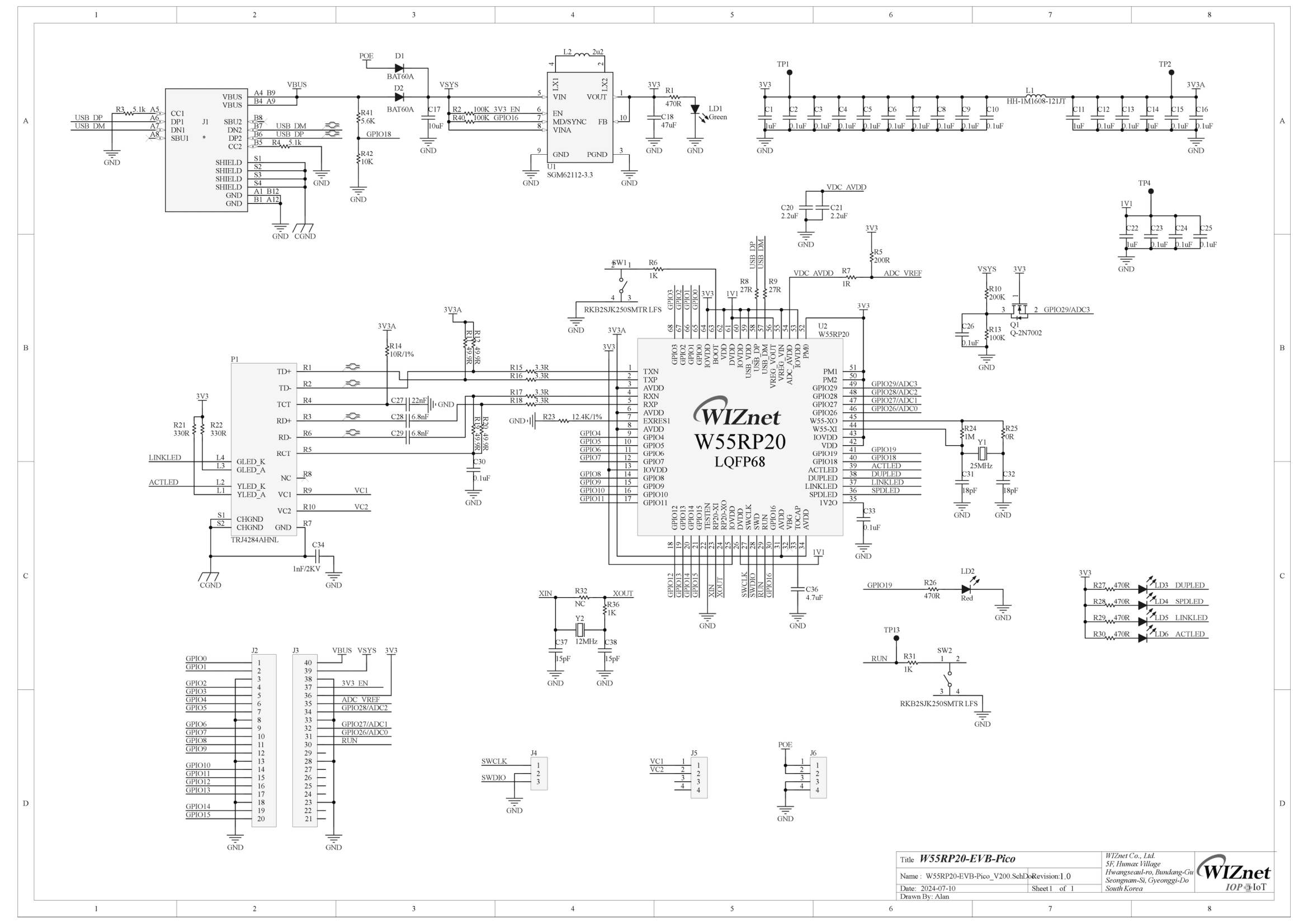
Schematic & Part list & Gerber File
3D File
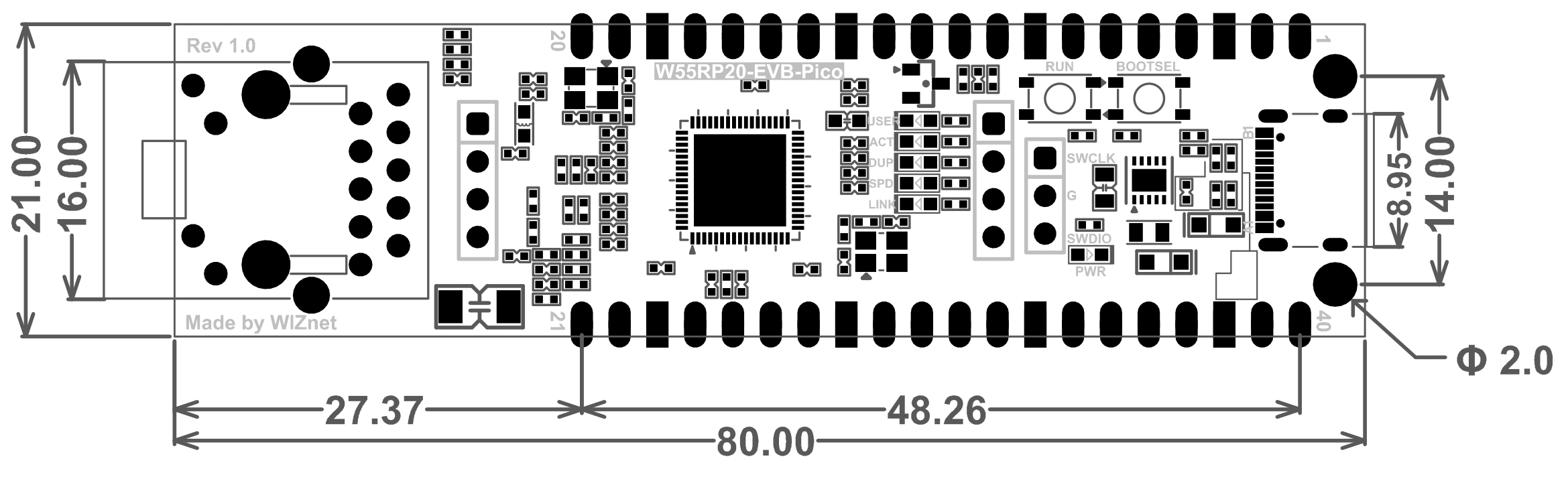
Dimension (Unit : mm)
Certification
AWS Qualification
W55RP20-EVB-Pico is RP2040-based device that got AWS IoT Core Qualification.

Firmware Example
Please refer to below links to find firmware example.
- C/C++
- MicroPython Examples
- CircuitPython Examples
- Arduino Examples
Application Notes
C/C++
- Ethernet Examples
- DHCP_DNS_EXAMPLE_AN_V100 - English
- FTP_Client_EXAMPLE_AN_V100 - English
- FTP_Server_EXAMPLE_AN_V100 - English
- HTTP_Server_EXAMPLE_AN_V100 - English
- LOOPBACK_EXAMPLE_AN_V100 - English
- MQTT_Publish_EXAMPLE_AN_V100 - English
- MQTT_Publish_Subscribe_EXAMPLE_AN_V100 - English
- MQTT_Subscribe_EXAMPLE_AN_V100 - English
- NETBIOS_EXAMPLE_AN_V100 - English
- SNTP_EXAMPLE_AN_V100 - English
- TCP_Client_over_SSL_EXAMPLE_AN_V100 - English
- TFTP_Client_EXAMPLE_AN_V100 - English
- UDP_multicast_receiver_EXAMPLE_AN_V100 - English
- AWS Examples
- Azure Examples
- LwIP Examples
How to buy
![]()
![]()