Pulse Width Modulation (PWM)
Introduction
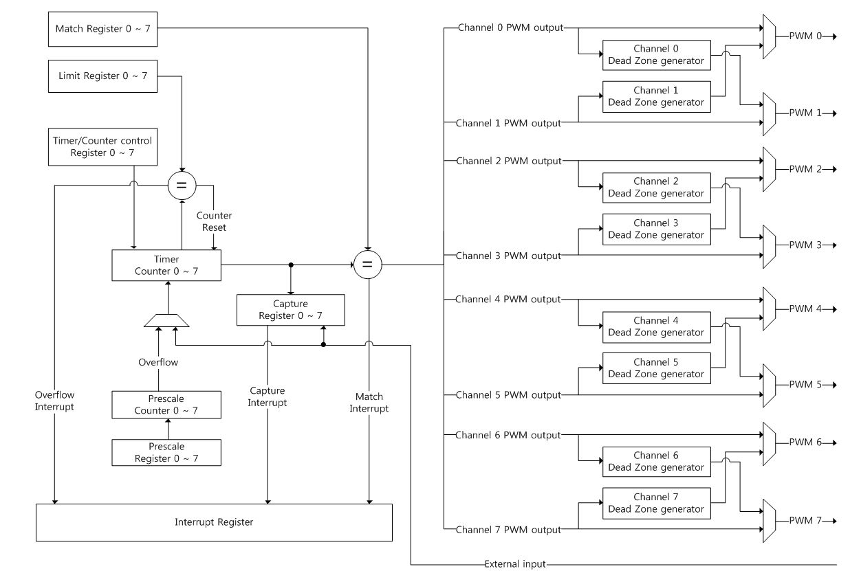
The PWM consists a 8-channel 32-bit Timer/Counter driven by a programmable prescaler. The function of the PWM is based on the basic Timer. Each timer and counter runs independently.
The PWM can be used to control the width of the pulse, formally the pulse duration, to generate output waveform or to count the counter triggered by external input.
Features
- Counter or Timer operation can use the peripheral clock, external clock source, or one of the capture inputs as the clock source.
- Eight independent 32-bit Timer/Counter driven by a programmable 6 bits prescaler runs as the PWM or standard timer if the PWM mode is not enabled.
- Eight PWM output waveforms.
- Each of Timer/Counter can have different or same clock source.
- Counter or timer operation.
- Eight capture registers that can take the timer value when an external input signal. A capture event can generate an interrupt signal optionally.
- 32-bit match register and limit register.
Functional description
Timer/Counter control
The PWM has 8 Timer/Counter clocks, which can be divided by a prescaler. Each Timer/Counter runs independently. The Timer/Counter is designed to count cycles of the clocks or external input signal and generate interrupts when specified timer values are occurred based on match register and limit register. The Timer/Counter can count up or down.
The PWM has match registers and limit registers. The match registers control the duty cycle of PWM output waveform. The limit registers control the period of the PWM output waveform. The Timer/Counter becomes 0 when it reaches value of the limit register. If PDMR(Periodic Mode Register) is set, the Timer/Counter counts repeatedly and if PDMR is reset, the Timer/Counter stops counting. Match register should be smaller than limit register(LR). If not, match interrupt is not occurred and PWM output waveform is always 1.
Repetition mode
The Timer/Counter has two repetition mode: periodic and one-shot mode. In periodic mode, the Timer/Counter recycles and then restarts when the Timer/Counter reaches the value of limit register. The below Figure shows periodic mode timing diagram

In one-shot mode, the Timer/Counter resets to the initial value and then stops when the Timer/Counter reaches the value of limit register. The below Figure shows one-shot mode timing diagram.

Counting mode
The Timer/Counter has two counting mode: Up-count and Down-count mode. In up-count mode, the Timer/Counter counts up from 0 to the limit register value and then recycles. If repetition mode is periodic, the Timer/Counter restarts and if repetition mode is one-shot mode, the Timer/Counter stops. The below Figure shows up-count mode timing diagram.

In Down-count mode, the Timer/Counter counts from 0xFFFF_FFFF, then recycles. If repetition mode is periodic, the Timer/Counter restarts and if repetition mode is one-shot mode, the Timer/Counter stops. The below Figure shows down-count mode timing diagram.

Timer and Counter mode
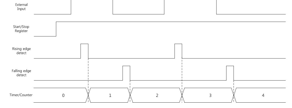
The Timer/Counter can run in timer mode or counter mode. In timer mode, the Timer/Counter is counted by PWMCLK after Prescale counter is overflowed. If prescale is set by 0, the Timer/Counter counts every PWMCLK period. In counter mode, the Timer/Counter is counted by external input signal. There are three counting method: rising edge, falling edge, and both edge. The counter mode has up-count or down-count mode and also has periodic or one-shot mode. The external input pin and PWM output pin are the same, so PWM output is disabled in counter mode.
The below Figure is counter mode example with rising edge mode. 
The below Figure is with falling edge mode.

The below Figure is with both rising and falling edge mode.
Prescaler description
The PWM has 6-bit prescale counter(PC) and the prescaler can divide the Timer/Counter clock frequency. Users can control it by Prescale Register(PR).
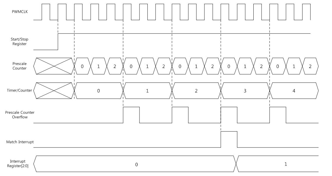
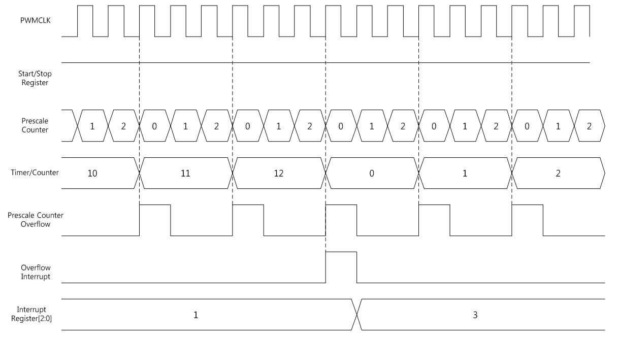
The below Figures show some examples of the Timer/Counter timing with prescale register is 2, match register is 2, limit register is 12, timer mode, periodic mode, up-count mode, and no interrupt clear.
The below Figure shows Timer/Counter timing diagram with match interrupt.
The below Figure Timer/Counter timing diagram with overflow interrupt.
PWM mode
Pulse Width Modulation mode generates a waveform with a period determined by the value of limit register and a duty cycle determined by the value of the match register.
The PWM output becomes always 1 when the Timer/Counter starts to count. Then the PWM output becomes 0 when the Timer/Counter reaches the value of match register. If the Timer/Counter is in periodic mode, the PWM output becomes 1 again when the Timer/Counter reaches the value of limit register. In one-shot mode, the PWM output does not change to 1 but stays 0 and the Timer/Counter stops.
The PWM mode can be selected independently on each channel(0~7) by PWM output enable and external input enable register. The external input pin and PWM output pin are the same, so external input is disabled in PWM mode.
The below Figure is an example of the PWM output waveform when the Timer/Counter is reached to the value of match register.

The below Figure is example of the PWM output waveform when to the Timer/Counter is reached to the value of limit register.

If match register is set as 0, the PWM output will be 1 while the Timer/Counter is 0. If the match register is bigger than the limit register, the PWM output is always 1.
Interrupt
The PWM has 8-bit interrupt enable register(IER) and each bit of IER corresponds to each interrupt of channel. Each PWM channel has Channel-n Interrupt Enable register(CHn_IER). The CHn_IER includes three types of interrupt: match, overflow, and capture. The match interrupt occurs when the Timer/Counter is reached to value of match register. The overflow interrupt occurs when the Timer/Counter is reached to value of limit register. The capture interrupt occurs when external input is entered for capture.
If interrupt occurs, corresponded bit of Channel-x interrupt register(CHn_IR) bit is set and PWM channel-n interrupt signal is generated. All CHn_IR is cleared by channel-n interrupt clear register(CHn_ICR) and then PWM channel-n interrupt signal is cleared.
Dead zone generation
Each PWM channel can output two complementary signals with dead zone time and it can be enabled by Channel-n Dead Zone Enable Register(CHn_DZER). Only 4 channels can be enabled because there are 8 PWM output pins. Channel 0 and 1 are a pair, channel 2 and 3 are a pair, channel 4 and 5 are a pair, and channel 6 and 7 are a pair. If users want to use channel-0 dead zone generation, channel-1 should be disabled. If channel 0 and 1 dead zone generation are enabled both, all outputs are 0. In that case, users should choose 1 channel.
Dead zone time are generated by the value of Channel-n Dead Zone Counter Register(DZCR). The dead zone counter counts up to value of DZCR. During the dead zone time, both complementary signals are both 0. Users have to adjust the signal depending on the devices that are connected to the outputs and their characteristics. If DZCR is bigger than the limit register, main output signal is toggled 0 to1 and then 1 to 0 while 1 PWMCLK and inverted output signal is always 0.
The below Figure shows two complementary PWM outputs with dead zone time. During dead zone time, both outputs are 0.

The below Figure shows a more detailed timing with dead zone counter.
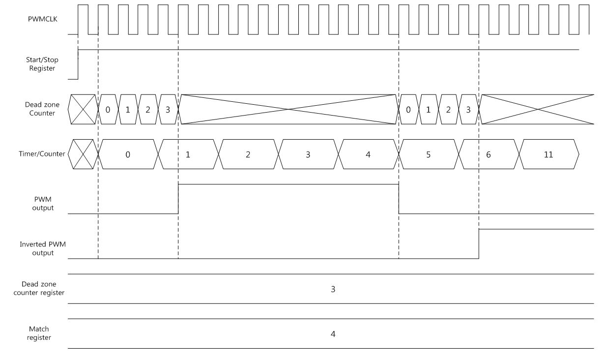
The dead zone counter and the Timer/Counter starts to count together and PWM output is 0 until dead zone counter is reached to value of dead zone counter register. The PWM output becomes 1 and 0 when the Timer/Counter is reached to value of match register. The inverted PWM output is also 0 until dead zone counter is reached to value of dead zone counter register. Then inverted PWM output becomes 1 after dead zone counter is reached to the value of dead zone counter register.
Capture event
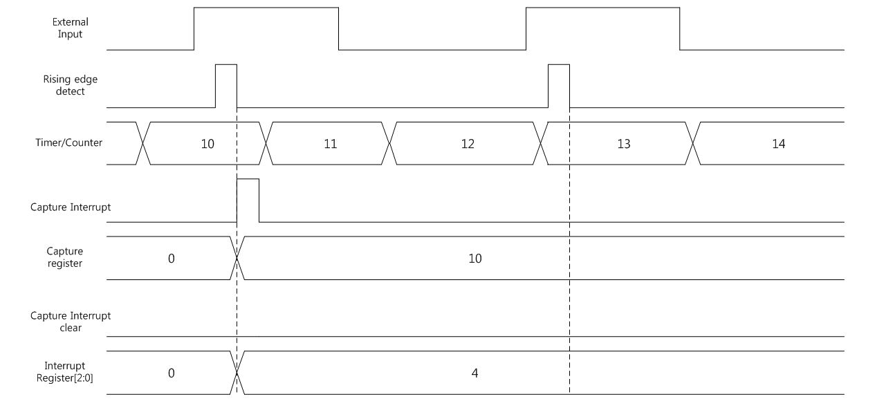
Each PWM channel can capture its Timer/Counter value when an external input signal changes. Any channel could use any method of rising or falling edges. If capture interrupt is enabled, capture interrupt occurs when the external input signal is toggled. The Timer/Counter value is saved in Channel-n Capture Register(CHn_CR) and the capture register is not overwritten until capture interrupt is cleared. The below Figure shows the capture event timing diagram. There is no interrupt clear, so second capture does not save during second rising edge detection.
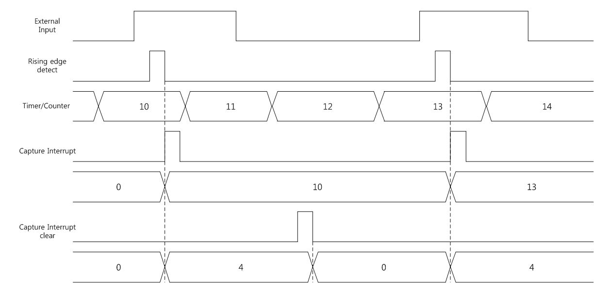
The below Figure shows, the capture event timing diagram with interrupt clear. The second capture is saved at the second rising edge detection because there is interrupt clear.
How to set the PWM
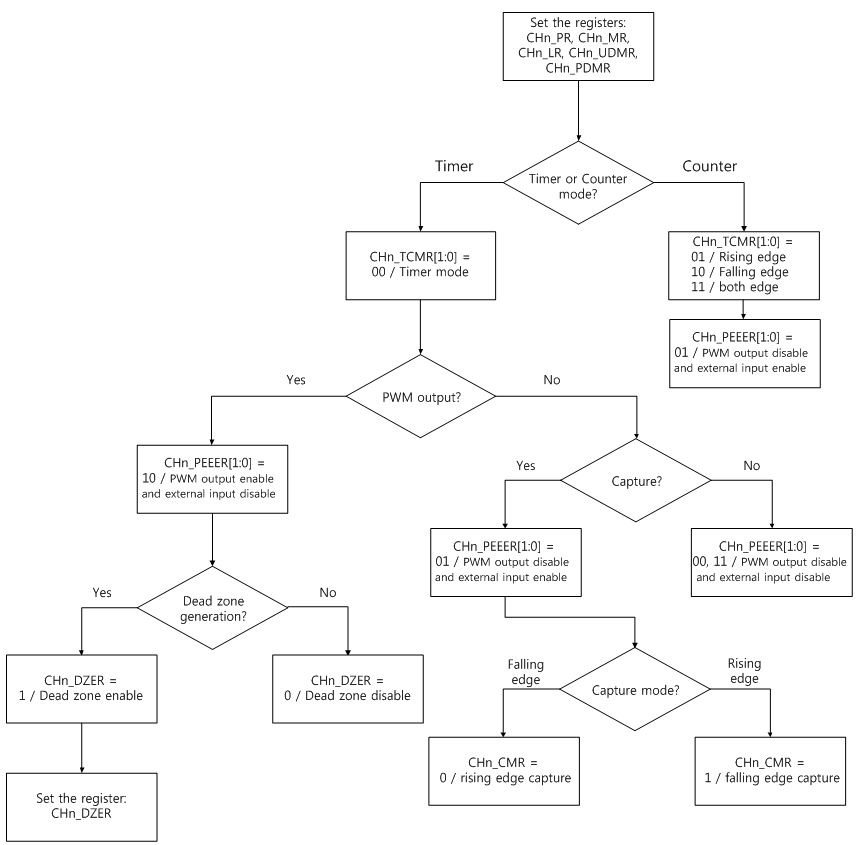
The below Figure shows the PWM setting flow step by step.
