Watchdog Timer (WDT)
Introduction
The watchdog is based on a 32-bit down-counter that is initialized from the Reload Register, WDTLoad. The watchdog generates a regular interrupt depending on a programmed value. The counter decreases by one on each positive clock edge of watchdog clock.
The watchdog monitors the interrupt and asserts a reset request signal when the counter reaches 0 and the counter is stopped. On the next enabled watchdog clock edge, the counter is reloaded from the WDTLoad Register and the countdown sequence continues. The watchdog reasserts the reset signal if the interrupt is not cleared by the time the counter next reaches 0.
The watchdog applies a reset to a system in the event of a software failure to provide a way to recover from software crashes. Users can enable or disable the watchdog unit as required.
Features
- 32-bit down counter.
- Internally resets chip if not periodically reloaded.
- The watchdog timer has lock register for to prevent rogue software from disabling the watchdog timer functionality.
- The watchdog timer clock(WDTCLK) and system clock(PCLK) are synchronous.
Functional description
Clock
The watchdog timer contains PCLK and WDTCLK clock inputs. PCLK is the main APB system clock and is used by the register interface.
Interrupt and reset request
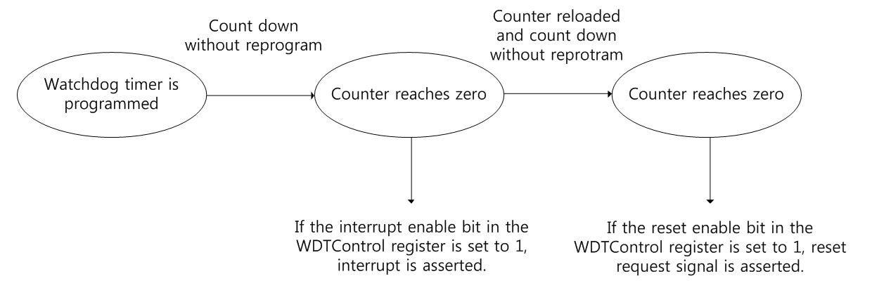
An interrupt is generated when the counter reaches 0 and is only cleared when the interrupt clear register is accessed. The register holds the value until the interrupt is cleared.
Reset request is asserted when the counter reaches 0 repeatedly and is not reprogrammed. Users can mask interrupts by writing 0 to the Interrupt Enable bit in the control register. Users can read the following from status registers:
- Raw interrupt status, before masking.
- Final interrupt status, after masking.
The below Figure shows Watchdog timer operation flow diagram