General Purpose Input/Outputs (GPIO)
Introduction
The GPIO(General-Purpose I/O Port) is composed of four physical GPIO blocks, each corresponding to an individual GPIO port(PORT A, PORT B, PORT C, PORT D). The GPIO supports up to 53 programmable input/output pins, depending on the peripherals being used.
Features
The GPIO peripheral consists of the following feature.
- GPIO_DATAOUT can SET/CLEAR by the SET register and CLEAR register.(1 for set and 0 for clear)
- Mask registers allow treating sets of port bits as a group leaving other bits unchanged.
- Up to 53 GPIOs, depending on configuration
- Programmable control for GPIO interrupts
- Interrupt generation masking
- Edge-triggered on rising, falling, or both
Functional description

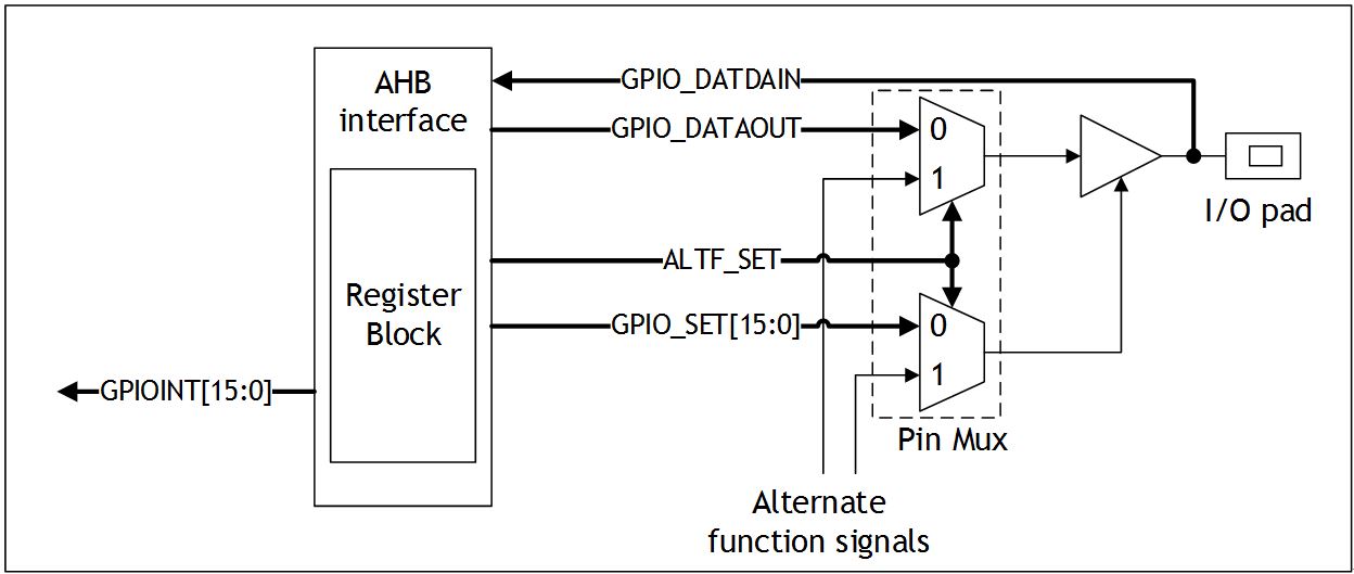
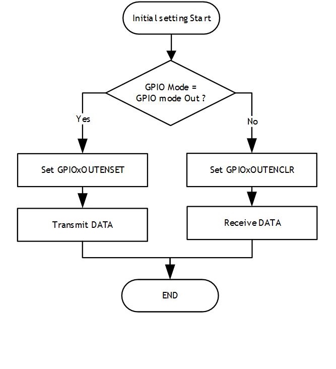
The below Figure shows the operation sequences available for the GPIO. The pad alternate function is using the pad alternate function select register. Refer to ‘Alternate Function Controller (AFC)’ for more details about each register. The pad control supports pull-down, pull-up, input buffer, and summit trigger input buffer. Refer to ‘Pad Controller (PADCON)’ for more details about each register.

Masked access
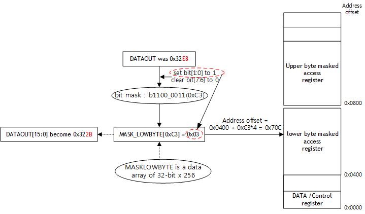
The masked access feature permits individual bits or multiple bits to be read from or written to in a single transfer. This avoids software-based read-modify-write operations that are not thread safe. With the masked access operations, the 16-bit I/O is divided into two halves, lower byte and upper byte. The bit mask address spaces are defined as two arrays each containing 256 words.
For example, to set bits[1:0] to 1 and clear bits[7:6] in a single operation, users can carry out the write to the lower byte mask access address space. The required bit mask is 0xC3, and users can write the operation as MASKLOWBYTE[0xC3] = 0x03.

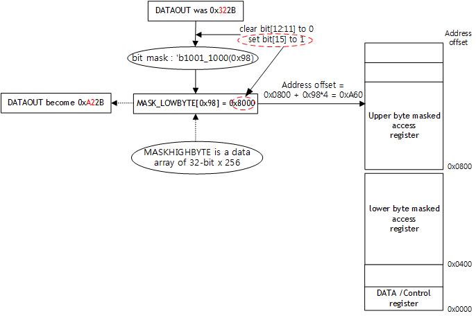
To update some of the bits in the upper eight bits of the GPIO port, users can use the MASKHIGHBYTE array as Figure below.
