Analog to Digital Converter (ADC)
Introduction
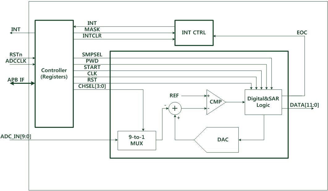
ADC is a 12bit analog-to-digital converter. It has up to 9 multiplexed channels allowing to measure signals from 8 externals and 1 internal source. ADC of various channels can be performed in single mode. The result of the ADC is stored in 12 bit register.
Features
- 12bit configuration resolution
- Conversion time : Max 10MHz (Sampling time can be programmable)
- 8 channel for external analog inputs
- CH0 : PC_15
- CH1 : PC_14
- CH2 : PC_13
- CH3 : PC_12
- CH4 : PC_11
- CH5 : PC_10
- CH6 : PC_09
- CH7 : PC_08
- 1 channel for internal LDO(1.5v) voltage.
- CH15 : Internal voltage
- Start of conversion can be initiated by software.
- Convert selected inputs once per trigger.
- Interrupt generation at the end of conversion.
Functional description
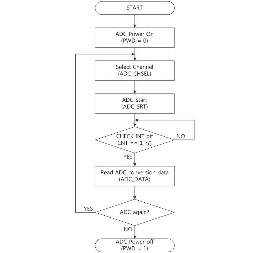
Operation ADC with non interrupt
The below Figure shows the flowchart of ADC operation with non-interrupt.
ADC can be used as below:
- ADC needs to be initialized before operation.
To initialize the ADC, clear the PWD bit first. - Select the ADC channel from 0 to 7 and 15 (initial core voltage).
- Run start ADC conversion by set ADC_SRT bit.
- Check INT bit to know finish of conversion.
- If INT bit is high (1), read ADC conversion data.
- Finally, ADC operation is finished by setting the PWD bit.
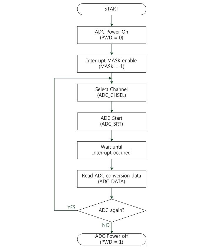
Operation ADC with interrupt
The below Figure shows the flowchart of ADC operation with interrupt. Operation is almost the same as the non-interrupt mode except checking INT register to know when enabling interrupt mask bit and conversion is completed.