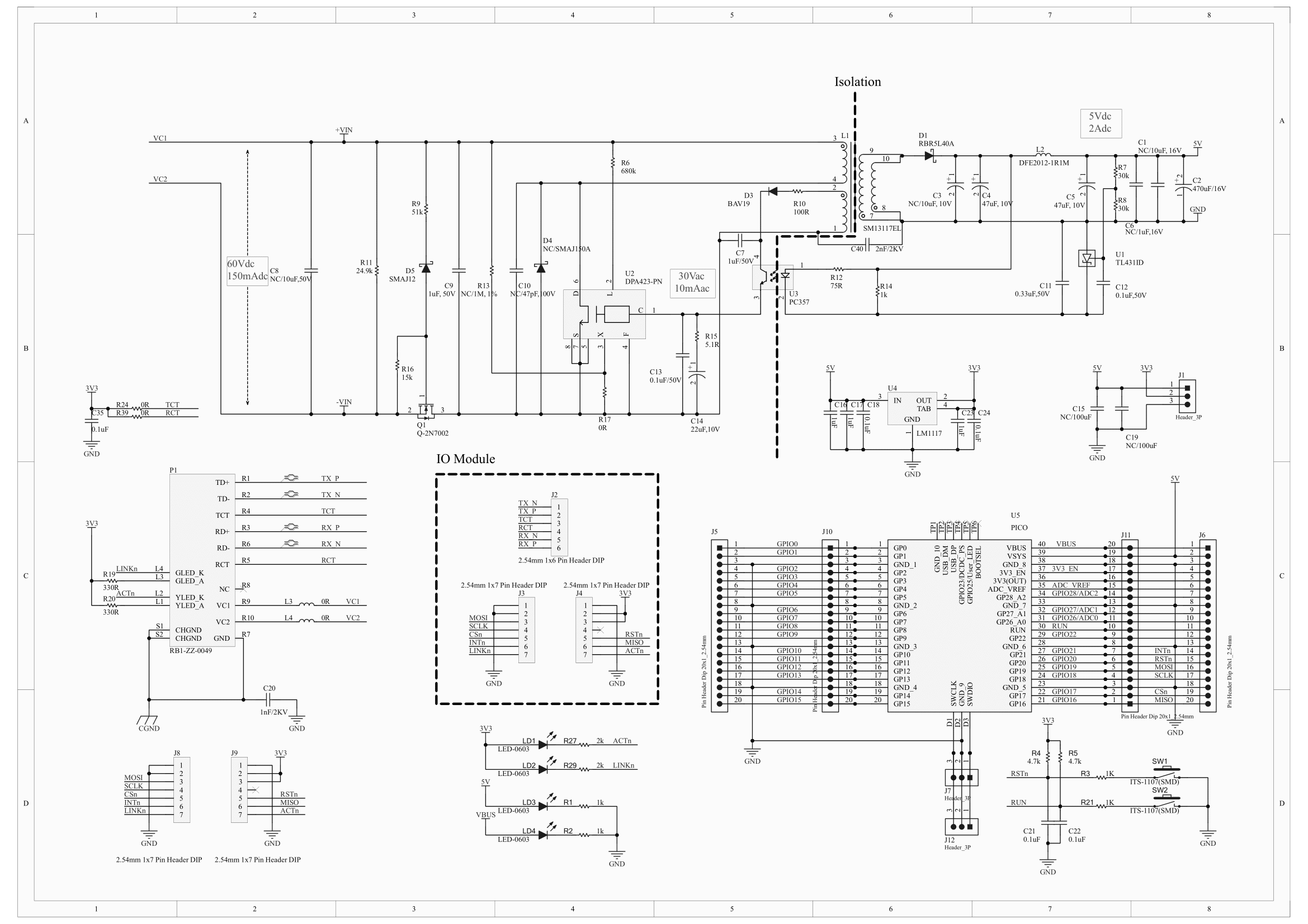
It combines with the W5500, W5100S, and W6100 Io Module to provide Ethernet as well as a separate power supply. It can supply up to 8W
- Raspberry Pi Pico Mountable
- Ethernet W5100S, W5500, W6100 IO Module Mountable
- IEEE802.3af compliant
- Mode A(Endspan), Mode B(Midspan)
- Wide input voltage range 37Vdc ~ 57Vdc
- Circuit Protection (OV,OC)
- High DC/DC conversion efficiency
- Isolation level 2kVrms
- Enhanced surge protection
- Internal build in 2 channel bridge rectifiers
| No | Value | Specification |
|---|
| 1 | Input Voltage | 37 ~ 57V |
| 2 | Output Voltage | 5V (1.6A) |
| | 3.3V (1A LDO) |
| 3 | Power | 8W |
| 4 | Switching Frequency | 400kHz fixed |
| 5 | Isolation | 2kVrms |
| 6 | Operating Temperature | -20 ~ 85℃ |
- W5100S-IO
- Supports Hardwired Internet Protocols: TCP, UDP, WOL over UDP, ICMP, IGMPv1/v2, IPv4, ARP, PPPoE
- Supports 4 Independent Hardware SOCKETs simultaneously
- Internal 16 Kbytes Memory for TX/ RX Buffers
- SPI Interface
- W5500-IO
- Supports Hardwired Internet Protocols: TCP, UDP, ICMP, IPv4, ARP, IGMP, PPPoE
- Supports 8 Independent Hardware SOCKETs simultaneously
- Internal 32 Kbytes Memory for TX/ RX Buffers
- Supports High Speed Serial Peripheral Interface(SPI MODE 0, 3)
- W6100-IO
- Supports Hardwired Internet Protocols: TCP, UDP, IPv6, IPv4, ICMPv6, ICMPv4, IGMP, MLDv1, ARP, PPPoE
- Supports 8 independent SOCKETs simultaneously with 32KB memory
- Internal 16 Kbytes Memory for TX/ RX Buffers
- SPI Interface
- RP2040 microcontroller with 2MByte Flash
- Dual-core cortex M0+ at up to 133MHz
- 264kByte multi-bank high performance SRAM
- External Quad-SPI Flash with eXecute In Place (XIP)
- High performance full-crossbar bus fabric
- 30 multi-function General Purpose IO (4 can be used for ADC)
- 1.8-3.3V IO Voltage (NOTE. Pico IO voltage is fixed at 3.3V)
- 12-bit 500ksps Analogue to Digital Converter (ADC)
- Various digital peripherals
- 2 × UART, 2 × I2C, 2 × SPI, 16 × PWM channels
- 1 × Timer with 4 alarms, 1 × Real Time Counter
- 2 × Programmable IO (PIO) blocks, 8 state machines total
- Flexible, user-programmable high-speed IO
- Can emulate interfaces such as SD Card and VGA
- 3-pin ARM Serial Wire Debug (SWD) port
- 10 / 100 Ethernet PHY embedded
- Supports Auto Negotiation
- Full / Half Duplex
- 10 / 100 Based
- Built-in RJ45(BR1-ZZ-0049)
- Built-in LDO (IL1117-3.3)
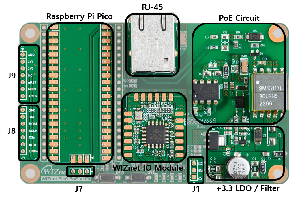
WIZnet IO Module pinout is directly connected to the GPIO of Pico Board as shown in the picture above. GPIO16, GPIO17, GPIO18, GPIO19, GPIO20, GPIO21 are connected to WIZnet IO Module. These pins enable SPI communication with WIZnet Chip to use Ethernet function. If you are using the Ethernet function, these pins cannot be used for any other purpose
| I/O | Pin Name | Description |
|---|
| I | GPIO16 | Connected to MISO on W5100S |
| O | GPIO17 | Connected to CSn on W5100S |
| O | GPIO18 | Connected to SCLK on W5100S |
| O | GPIO19 | Connected to MOSI on W5100S |
| O | GPIO20 | Connected to RSTn on W5100S |
| I | GPIO21 | Connected to INTn on W5100S |
| I | GPIO24 | VBUS sense - high if VBUS is present, else low |
| O | GPIO25 | Connected to user LED |
| I | GPIO29 | Used in ADC mode (ADC3) to measure VSYS/3 |
| Pin No. | Pin Name | Description |
|---|
| PIN40 | VBUS | Micro-USB input voltage, connected to micro-USB port pin 1. Nominally 5V. |
| PIN39 | VSYS | Main system input voltage, which can vary in the allowed range 4.3V to 5.5V, and is used by the on-board LDO to generate the 3.3V . |
| PIN37 | 3V3_EN | Connects to the on-board LDO enable pin. To disable the 3.3V (which also de-powers the RP2040 and W5100S), short this pin low. |
| PIN36 | 3V3 | Main 3.3V supply to RP2040 and W5100S, generated by the on-board LDO. |
| PIN35 | ADC_VREF | ADC power supply (and reference) voltage, and is generated on W5100S-EVB-Pico by filtering the 3.3V supply. |
| PIN33 | AGND | Ground reference for GPIO26-29. |
| PIN30 | RUN | RP2040 enable pin, To reset RP2040, short this pin low. |
| Pin No. | Pin Name | Description |
|---|
| 1 | +5V | +5V Power I/O Pin |
| 2 | +3.3V | +3.3V Power I/O Pin |
| 3 | GND | Ground |
3-pin ARM Serial Wire Debug (SWD) port
| Pin No. | Pin Name |
|---|
| 1 | SWDIO |
| 2 | GND |
| 3 | SWCLK |
| Item | Description |
|---|
| Operation Temperature MAX | 70℃ |
| Input Volatge | 48 ~ 57V |