SPI mode Guide
1. Introduction
The W55RP20-S2E operates in SPI Slave Mode and can be controlled using AT Commands. The maximum SPI clock speed supported in this mode is 10 MHz. To communicate with the MCU, it is need to connect the SPI pins and set the UART_SPI_SEL (GPIO13) pin to High to use SPI. Refer to Figure 1 for the W55RP20-S2E SPI Pinout.
When the W55RP20-S2E (SPI Slave) needs to send data, the SPI_INT (GPIO26) signal should be set to Low so that the SPI Master can read it.
2. Github Link
-
The SPI Master code for W55RP20-S2E can be found at:
3. Pinout
| Fuction | Pin Number | Symbol | Description |
|---|---|---|---|
| SPI_SCK | 67 | GPIO2 | SCK input pin for Data SPI transmission (SPI MODE) |
| SPI_MISO | 68 | GPIO3 | MISO pin for Data SPI reception (SPI MODE) |
| SPI_MOSI | 9 | GPIO4 | MOSI pin for Data SPI transmission (SPI MODE) |
| SPI_CSn | 10 | GPIO5 | SPI Chip Select pin (SPI MODE) |
| SPI_INT | 46 | GPIO26 | SPI Master Recv data pending pin |
| UART_SPI_SEL | 19 | GPIO13 | UART/SPI interface select pin (High:SPI, Low/NC:UART) |
| Debug_UART_TX | 65 | GPIO0 | TX pin for Output Debug Messages |
| Debug_UART_RX | 66 | GPIO1 | RX pin for Output Debug Messages |
4. SPI Frame Format
The W55RP20-S2E operates based on SPI Frames transmitted by the SPI Master. The SPI Frame Format consists of DATA Frame and AT CMD Frame.
All commands are 4 bytes long. For example, the Data Read Command consists of:
- 1-byte command (0xB0)
- 3 dummy bytes (0xFF * 3)
4.1 Master Data Frame
4.1.1 TX Data Frame
To transmit TCP or UDP data, follow these steps:
- The Master writes 0xA0 to initiate data transmission, specifies the Data Length (2 bytes) with the size of the data to be sent, and transmits it along with 0xFF (Dummy Byte), forming a total of 4 bytes.
- The Master waits by sending 0xFF until the Slave responds with *ACK.
- The Slave responds with 0x0A + 3 dummy bytes (0xFF) to indicate ACK.
- The Master transmits the data in the Data Phase.
- After completion, the Slave transmits an ACK.
*NACK : If the Master sends a Data Length exceeding 2048 bytes or if the Slave is not connected to a network, it responds with NACK (0x0B + 3 dummy bytes (0xFF)).
 |
| Figure: SPI TX Data Frame ① |
 |
| Figure: SPI TX Data Frame ② |
4.1.2 RX Data Frame
To receive TCP or UDP data, follow these steps:
- When the SPI_INT signal goes Low, the Master initiates a read operation.
- The Master writes 0xB0 and sends 3 dummy bytes (0xFF).
- The Master waits by sending 0xFF until the Slave responds.
- The Slave responds with 0xB1, Data Length (2 bytes in Little Endian), and 0xFF (Dummy Byte).
- The Slave sends the data in the Data Phase.
- Upon completion, the SPI_INT signal is set to High.
 |
| Figure: SPI RX Data Frame ① |
 |
| Figure: SPI RX Data Frame ② |
4.2 Master AT CMD Frame
4.2.1 AT CMD TX(SET) Frame
To send an AT command, follow these steps:
- The Master sends the first 2 bytes of the AT command.
- Since AT CMD mode requires sending 0x0D and 0x0A at the end of the message, the Master transmits the Data Length by subtracting 2 from the total message length. The Data Length is specified as a 2-byte value using little-endian format.
- The Master waits by sending 0xFF until the Slave responds with ACK.
- The Slave responds with 0x0A and 3 dummy bytes (0xFF) as ACK.
- The Master transmits the remaining AT command data.
- Upon completion, the Slave sends an ACK.
Note: refer to the AT Command Manual document for details on the AT CMD format.
 |
| Figure: SPI AT CMD TX(SET) Frame ① |
 |
| Figure: SPI AT CMD TX(SET) Frame ② |
4.2.2 AT CMD RX(GET) Frame
To get an AT command response, follow these steps:
- Since AT CMD mode requires sending 0x0D and 0x0A at the end of commands, the Master transmits a 4-byte AT command, including these characters, to the Slave.
- After the transmission is complete, the Slave sets the SPI_INT signal to Low to respond with the AT CMD data.
- The Slave responds with 0xB1, Data Length (2 bytes in Little Endian), and 0xFF (Dummy Byte).
- The Slave transmits the AT command data response.
- When the Master completes reading the AT CMD data, the Slave sets the SPI_INT signal to High.
Note: refer to the AT Command Manual document for details on the AT CMD format.
 |
| Figure: SPI AT CMD RX(GET) Frame ① |
 |
| Figure: SPI AT CMD RX(GET) Frame ② |
5. Operation
5.1 Data Operation
5.1.1 TX Data Opertion
To transmit TCP or UDP DATA, proceed as followings.
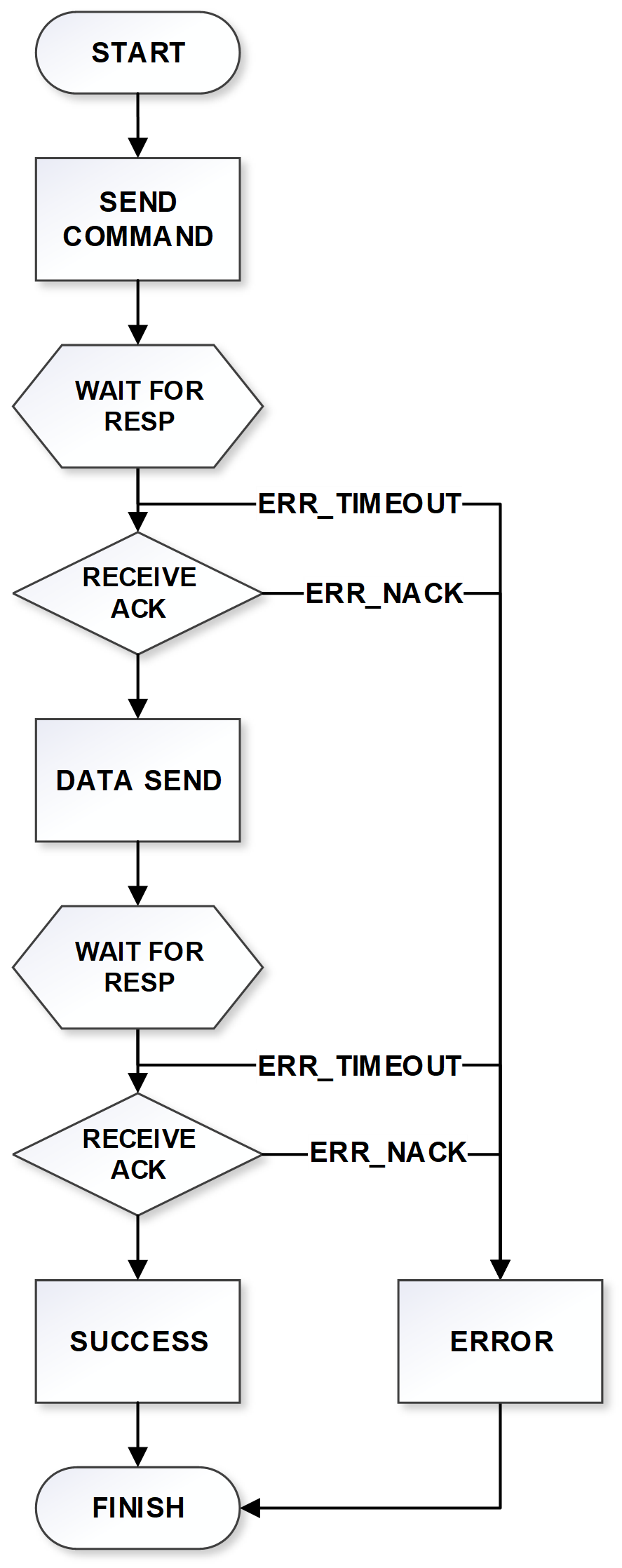 |
| Figure: SPI TX Data Operation Flowchart |
5.1.2 RX Data Operation
To receive TCP or UDP DATA, proceed as followings.
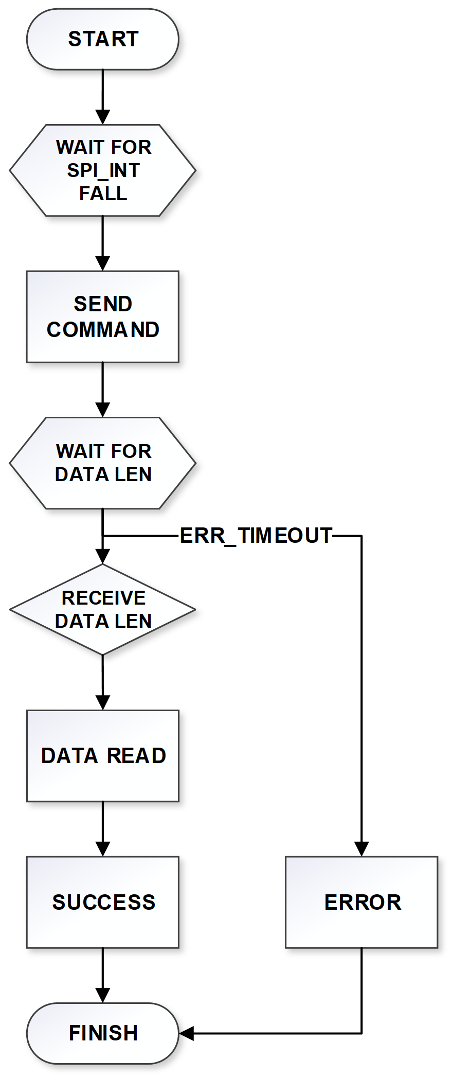 |
| Figure: SPI RX Data Operation Flowchart |
5.2 AT CMD Operation
5.1.1 AT CMD TX(SET) Operation
To transmit AT commands, proceed as followings.
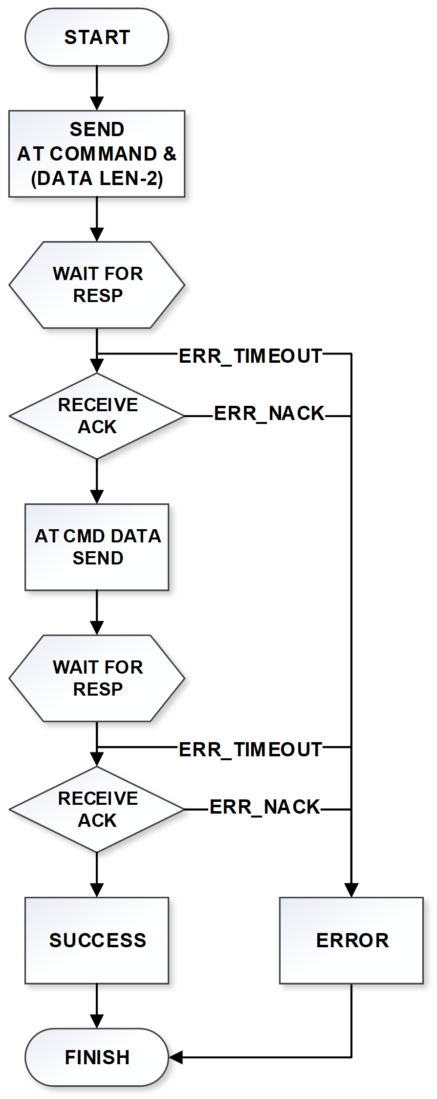 |
| Figure: SPI AT CMD TX(SET) Operation Flowchart |
5.1.2 AT CMD RX(GET) Operation
To receive AT commands, proceed as followings.
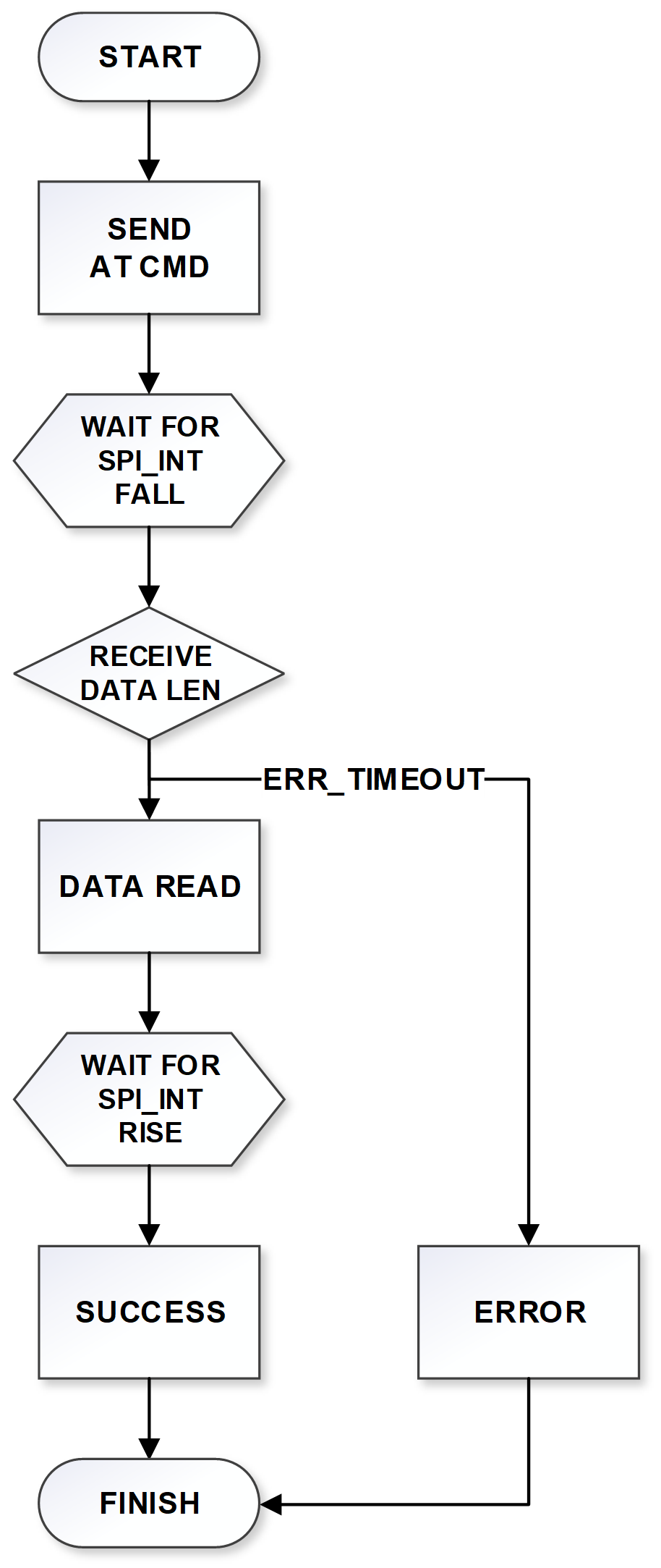 |
| Figure: SPI AT CMD RX(GET) Operation Flowchart |