Config tool Guide
Overview
This documentation provides detailed usage of the Config-tool.
Config tool support list and downloads
Wiznet Configuration tool is a configuration tool that allows you to search, change settings, upload firmware, and more for products on the network.
The Configuration Tool is publicly available on Github under the name WIZnet-S2E-Tool-GUI on the WIZnet page on Github under the name WIZnet-S2E-Tool-GUI, and the latest version of the executable can be downloaded from the release page of that repository.
Built on Python, it runs on any OS.
- Github repository: WIZnet-S2E-Tool-GUI Github repository
- Download the latest version: WIZnet-S2E-Tool-GUI Github repository: Release
Configuration Tool Layout
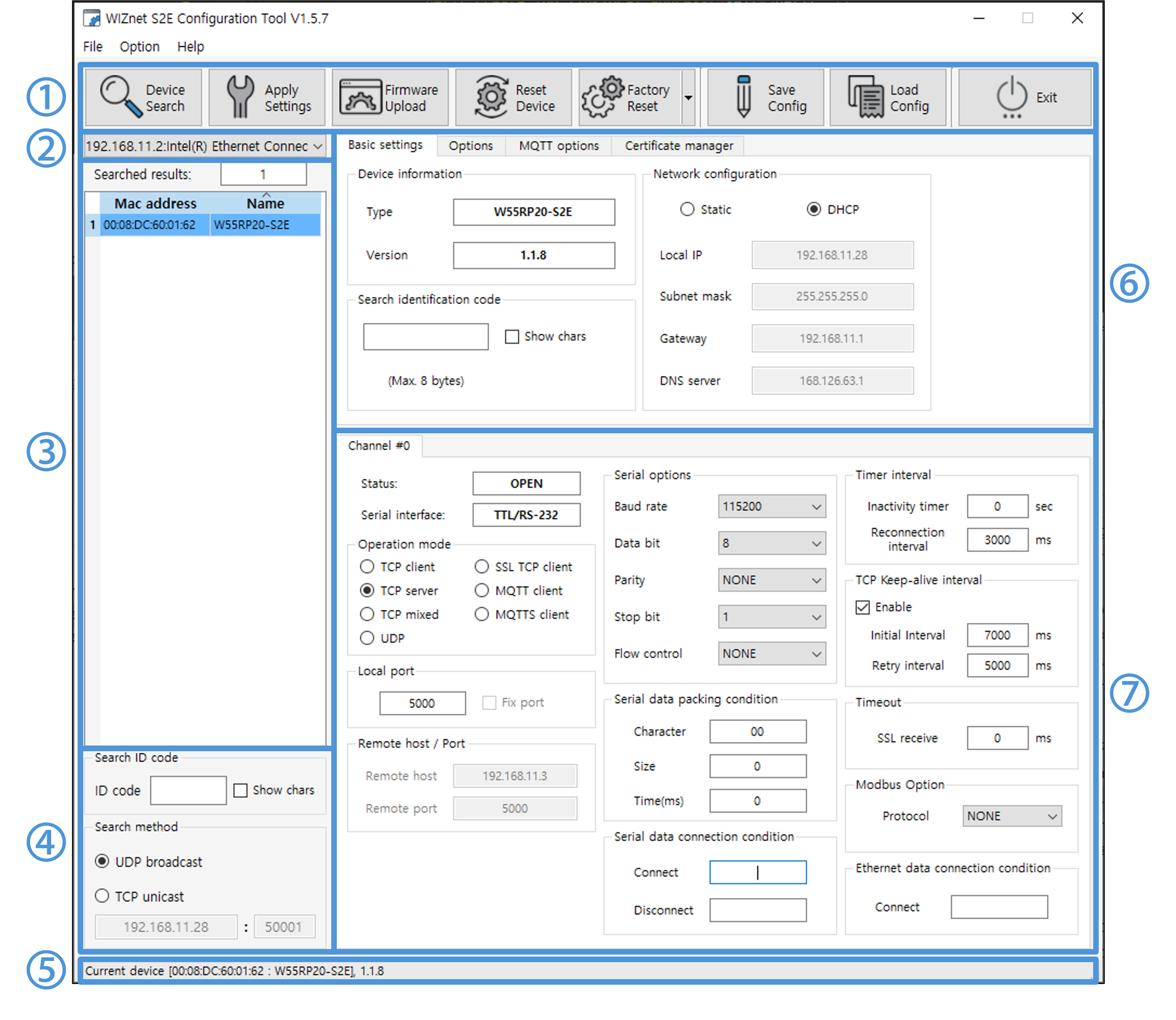
After installing and running the program, you can see the following launch screen.
 |
| Figure: Configuration Tool Layout |
The Settings program can be divided by function, as shown in the image above.
① Top side Icon Menu
-
Located at the top of the Configuration tool, you can search for products,upload firmware,restart,initialize, etc.

Figure: Icon Menu -
1) Device Search
- Search for connected devices on the same network.
- You can search by UDP Broadcast (search for modules in the network, multiple module products can be searched) and TCP Unicast (search for a single module).
- Device search using the network uses TCP/UDP port 50001. If a firewall or antivirus program is blocking that port, device search might fail.
- In these cases, we recommend disabling your firewall or antivirus program before testing.
- If you are using multiple network adapters, packet forwarding might fail depending on the network interface metric priority.
Disable all but one network adapter you are using in your OS settings and test again.
When using a virtual machine (VM) such as VMware or Virtual Box, this situation can be caused by a 'virtual Ethernet adapter' created for the VM's networking.
Disable virtual machines (VMs) such as VMware or Virtual Box, or search for TCP Unicast.
-
2) Apply Settings
- Save the changed settings and apply them to the device.
- If the setting change is successful, it is reflected in the Configuration tool.
- The product automatically reboots after the action is complete.
-
3) Firmware Upload
Never power off during a firmware upload
This can cause the product to malfunction- Select the firmware binary file provided by Wiznet to update the product firmware.
- The product will automatically reboot after the operation is complete.
- After successful firmware upload, you can see the following message pop up.
Figure: Popup Message - Firmware Upload Successfully - The ability to upload device firmware over the network uses TCP port 50002. If the port is blocked by a firewall or antivirus program, the device firmware upload might fail.
In these cases, we recommend disabling your firewall or antivirus program before testing. - When updating the firmware, the PC on which Config-tool is running must match the IP band of the device.
When using DHCP mode (automatic IP assignment), configure your PC and the product to receive IP assignments from the same router.
When using Static mode (direct IP assignment), set it up like this example
ex) Device IP : 192.168.11.2
PC IP: 192.168.11.3 (another IP address in the same Class C private IP band) - If you have performed an upload with incorrect firmware, we cannot guarantee the normal operation of the product.
-
4) Reset Device
- Restarts the selected device.
-
5) Factory Reset
- Resets the device's settings to the factory default values.
- The device automatically reboots after the operation is completed.
-
6) Save Config
- Saves all current settings of the selected device to a file.
- This can be useful when environmental changes require reconfiguration or when applying the current settings to another device.
-
7) Load Config
- Loads the settings from a file saved by the Save Config function.
- After loading, press the "Apply Settings" button to apply these settings to the device.
-
8) Exit
- Exits the Configuration tool.
② Network Interface configuration
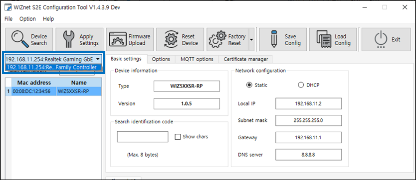
- If you use multiple types of network adapters, you'll see a list of adapters and the bands they're using, and you can choose which network band to use based on your environment.
 |
| Figure: Network adapters |
③ Searched Device List
 |
| Figure: Device List |
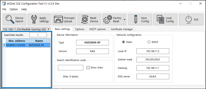
- A list of devices found through the Search function is displayed.
- Searched results shows the number of devices found.
- Each device is identified by its MAC address and device name.
- Click a found device to select it.
④ Search ID code & Search method
 |
| Figure: Search ID code & Search method |
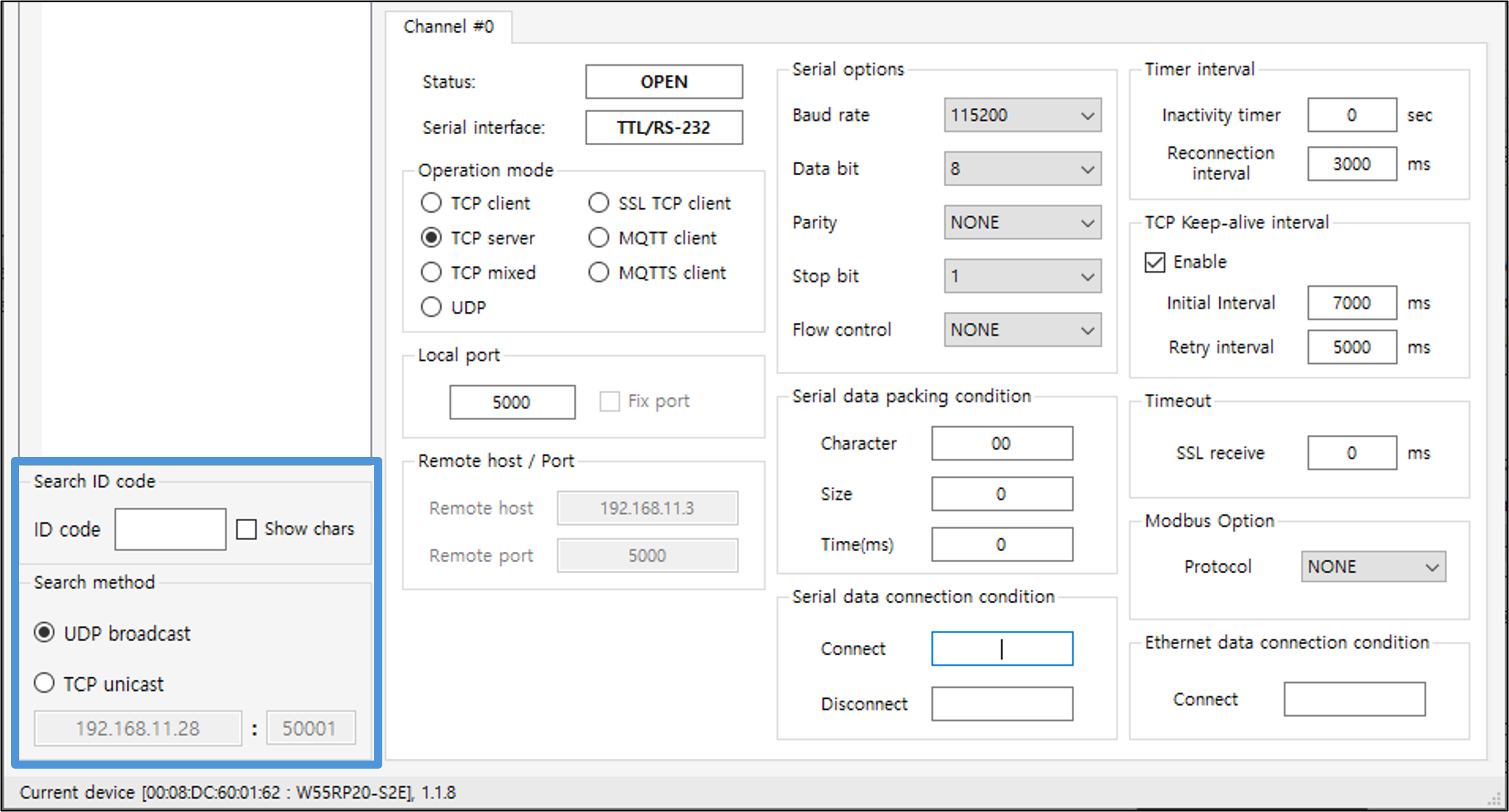
- Search ID code
- If a search identification code is set, then this is where you enter the code.
- The same code must be entered when searching for a product to be displayed in the product list.
- Search method
- Select a product search method.
- The default value is UDP broadcast.
- UDP broadcast can search for modules in the network, and multiple module products can be searched.
- TCP unicast uses a specific device's IP and port 50001 to discover only one device.
When used in conjunction with your router's port forwarding feature, you can discover devices and change settings from the outside local network.
⑤ Status bar
 |
| Figure: Status bar |
- Displays the process and results of a search action.
If there are multiple devices, the MAC addresses of the devices you select are displayed together. - When performing a firmware update, a progress bar is displayed alongside it.
⑥ General options
-
Viewing and changing product details settings
-
Configure with Preferences Basic settings / Options / MQTT Options / Certificate Manager tab (as of W55RP20-S2E)
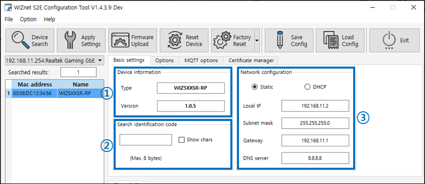
Figure: Basic settings Tab 1) Device information
- Type shows the name of the selected device, Version shows the version of the firmware of the device.
2) Search identification code
- Scope and delimiter: a string of up to 8 bytes
- Default: Null (Not use)
- The Search identification code is an option for identification when searching for products.
- If this option is set, then the same code that is set when searching for a product must be entered to appear in the list of discovered devices.
3) Network configuration
- Static (default)
- Select Static IP address assignment mode. When you select this option, the Local IP, Subnet mask, Gateway, and DNS server fields are enabled for entry.
You can set both a public IP address and a private IP address. - If you're using a TCP client or TCP mixed mode, a DNS address must be set if the remote destination host to which you want to forward data is a domain name rather than an IP address.
- Select Static IP address assignment mode. When you select this option, the Local IP, Subnet mask, Gateway, and DNS server fields are enabled for entry.
- DHCP
- This is a way to get an IP address automatically through a DHCP server built into a router (NAT Router).
It is common to assign a private IP address from the router's dynamic IP assignment range, but it is also possible to assign a public IP address. - The DHCP server side assigns both the IP address and gateway address, subnet mask, and DNS address, so you don't need to do any configuration.
- This is a way to get an IP address automatically through a DHCP server built into a router (NAT Router).
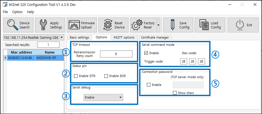
Figure: Options Tab 1) TCP Timeout
- You can set the TCP retransmission retry count.
- Value: 1~255
2) Status pin
- Enable the flow control functions DTR, DSR.
3) Serial debug
- When this option is set, the Debug UART will output information about the product and error conditions.
- The serial setting for the Debug UART is fixed at 921600-8-N-1:None.
- When the Enable with Data option is set, you can monitor Serial to Ethernet (S2E) or Ethernet to Serial (E2S) data.
4) Serial command mode
- When checked, switch from data transmission mode (GW mode) to serial command mode (AT mode) when receiving a command mode switch code during serial data, Default: Enabled
- In serial command mode, you can change and monitor various settings of the product using 2-byte serial commands (AT CMD).
- When you change to serial command mode, any existing TCP connections are disconnected.
- Trigger code
- Entering the set trigger code as serial data enters AT mode
- Default: [2B][2B][2B] (+++)
- The value of each byte recognizes only HEX codes.
5) Connection password(TCP server mode only)
- 최대 8-byte string
- Default: Null(not ues)
- Connection password can only be enabled in TCP server mode (also possible when connecting as a TCP Server in TCP mixed mode).
- If the TCP client does not send the connection password within 5s after connecting to the device, the TCP connection is automatically disconnected.
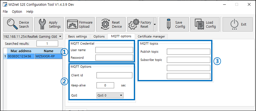
Figure: MQTT Options Tab 1) MQTT Credentials
- User name, Passworkd
- MAX 128
- Can be set to blank
2) MQTT Option
- Clinet ID
- MAX 128
- Can be set to blank but not recommend
- Keep Alive
- Can be set from 0 to 65535
- Set to 0 when not in use
- QoS
- 0,1,2 selectable
3) MQTT Topics
- Publish Topic
- MAX 128
- Subscribe Topic
- MAX 128
- subscribe topics up to 3
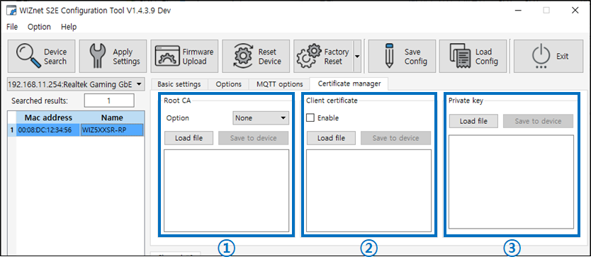
Figure: Certificate Tab 1) Root CA
- Option : None, Optional, Verify Three options to choose from
- Load File : Load a pre-saved Root CA file
- Save to device: Save the imported file to your device
2) Client Certificate
- Enable check box : Enable on check
- Load File : Load a pre-saved Root CA file
- Save to device: Save the imported file to your device
3) Private Key
- Load File : Load a pre-saved Root CA file
- Save to device: Save the imported file to your device
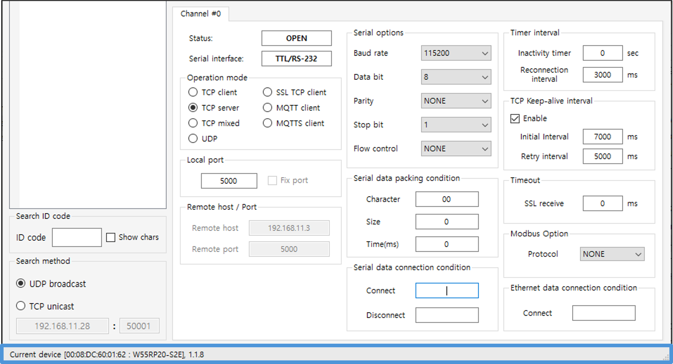
⑦ channel options
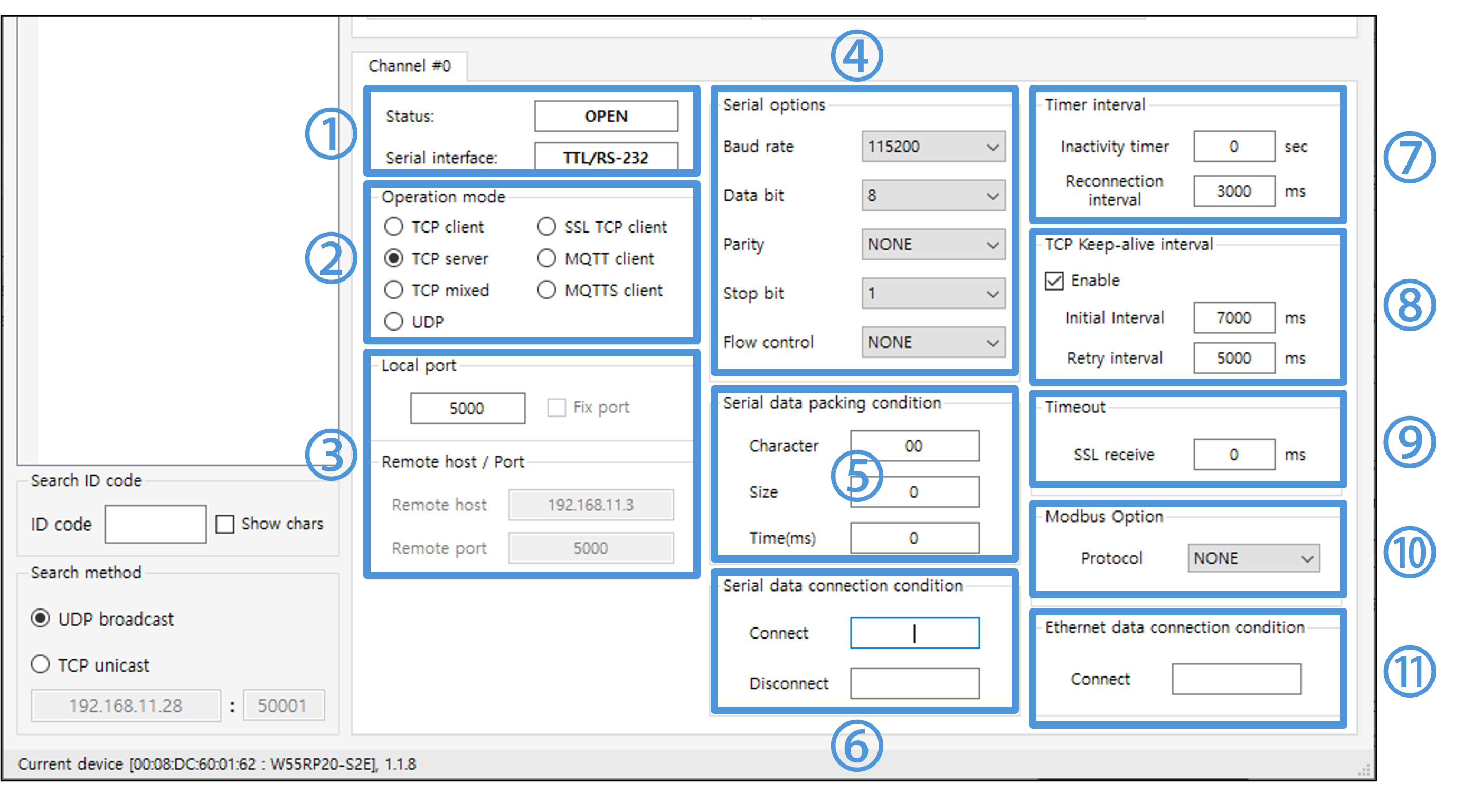 |
| Figure: Channel Tab |
1) Status & Serial Interface
- Status
- BOOT : This is the boot entry state and allows you to update the product's settings and firmware.
- OPEN : The state before a TCP connection is established
- CONNECT : TCP connection established
- UPGRATE : Updating firmware or assigning DHCP IPs
- ATMODE : Serial AT Command Mode Status
- UDP : UDP Mode Status
- Serial Interface
- The type of serial interface
2) Operation mode
- Set the device's network behavior mode
- Choose from four modes to fit your application and goals: TCP client mode, TCP server mode (default), mixed TCP client/server mode, and UDP mode
- TCP Client
- Attempts a TCP connection to the specified destination (TCP server) and communicates with the connected TCP server if the connection succeeds.
- TCP Server
- Listens for connection requests from TCP clients and establishes a TCP connection when a client connection request is received, allowing data to be sent/received on a successful connection.
- TCP MIX
- When operating as a TCP server and waiting for a connection from a TCP client after setting up, when serial data is input,
it exits the TCP server mode and switches to TCP client mode and attempts to connect to the entered remote host IP and port to establish a TCP connection
If data transmission or reception is not made within the set time (Inactivity timer) after the TCP connection, the device disconnects from the TCP server and operates in TCP server mode, which is the initial operating state of TCP MIX mode.

- When operating as a TCP server and waiting for a connection from a TCP client after setting up, when serial data is input,
- UDP
- 1:1 UDP mode
- Communicate to the set remote destination host address (domain name) and port number.
- 1:N UDP Boradcast
- If you set the remote host IP to 192.168.x.255, you can boardcast data to devices in the 192.168.x band that have an open remote port set on the device.
- 1:N UDP Response mode
- Available when Remote host IP is set to 0.0.0.0
- Can send data to the destination from which it was sent
The destination address changes to the new destination address when data is received from another destination - It can be utilized in applications that send data from multiple UDP destinations, to which a serial device responds.
- 1:1 UDP mode
- TCP Client
3) Local port, Remote host / Port
- Local port
- Ports the device opens
- Remote host
- The IP of the destination that the device connects to when it's a client, which is the IP of the server.
- Remote port
- The port of the destination to which the connection is made when Dabais is the client, i.e., the port opened by the server.
4) Serial Options
- Baud Rate
- surpport 300, 600, 1200, 1800, 2400, 4800, 9600, 14400, 19200, 28800, 38400, 57600, 115200(default), 230400, 460800, 921600
- Data bit
- surpport 7, 8(default)
- Parity
- surpport NONE(default), ODD, EVEN
- Stop Bit
- surpport 1(default), 2
- Flow Control
- NONE(default): not use flow control
- XON/XOFF: Software flow control
- CTS/RTS: Hardware flow control
5) Serial data packing condition
- Various serial data packing options so that serial data can be collected and transmitted according to user's conditions
When utilized, user command frames or cyclic data that need to be sent at once can be collected and sent. - Application priority is Character => Size => Timer and can be set to overlap
- Timer
- 0~65535(ms), Default is 0 (unused)
- Buffer data for a specified time and send it all at once
- Size
- 0~255(byte), Default is 0 (unused)
- Stores data in a buffer until the specified data size is reached, then sends it all at once
- Character
- 1-byte Character(Hex code), Default is 0 (unused)
- Stores data in a buffer until the specified character is entered, and then sends it all at once, including the specified character, when the specified character is in the data.
If the buffer size is exceeded, send only data excluding the specified characters.
6) Serial data connection condition
- This function is useful for notifying serial devices or systems of changes in network connection status.
- Sends a predefined string to the serial port when the Ethernet connection status changes.
- Available in WIZnet-S2E-Tool-GUI version 1.5.7 or later and firmware version 1.1.8 or later.
- Connect message
- Sends the configured string (up to 30 characters) to the serial port when a TCP or UDP connection is established.
- Disconnect message
- Sends the configured string (up to 30 characters) to the serial port when a TCP or UDP connection is closed.
7) Timer interval
- Inactivity timer
- 0 ~ 65535(s), Default is 0 (unused)
- When the Inactivity timer is set, it terminates the connection after a specified amount of time without sending data since the last data transfer.
- UDP does not apply
- Reconnection interval
- 0 ~ 65535(ms), Default is 3000 (3 seconds applied)
- The Re-connection interval determines the interval between TCP connection retries for TCP client behavior (including TCP clients in a TCP mix).
- This option is required for reconnection attempts if a TCP connection attempt fails.
- It must be set to at least 1 ms.
8) TCP Keep-alive interval
- When this option is checked, keep-alive packets are sent when the product is operating in TCP mode (including TCP Server, TCP Client, and TCP MIX) to maintain connectivity.
- If there is no response to the keepalive packet, the TCP connection is closed. (Socket close / disconnect)
- The device starts sending keepalive packets after it has sent at least one Ethernet packet.
- Since Ethernet network equipment cannot detect a physical disconnection of remote equipment, it is recommended that you enable this option so that you can terminate the TCP connection in problem situations.
In particular, when operating in TCP server mode, if you do not have a setting to send keepalive packets, you may find yourself in a situation where you are unable to terminate an existing connection if the remote device performs a shutdown/reconnect during a physical disconnect for some reason.- Initial interval
- 0 ~ 65535(ms), Default is 7000 (7 seconds applied)
- Interval before sending the first keepalive packet
- Retry intercal
- 0 ~ 65535(ms), Default is 5000 (7 seconds applied)
- The interval between sending each keepalive packet
- Initial interval
9) Timeout
- 0 ~ 60000(ms), Default is 2000 (2 seconds applied)
- Raise a timeout if no SSL response by a specified time
- Works only in SSL TCP client mode
10) Modbus Option
- WIZnet-S2E-Tool-GUI version 1.5.5 or higher is required to use the Modbus protocol.
- Operation mode
- Make sure to select TCP Server or UDP mode in the Operation mode settings.
- protocol
- The serial protocol supports both RTU and ASCII modes and can be selected based on system requirements.
- Modbus Poll connects via Modbus TCP/IP or UDP/IP, depending on the configuration.
- Modbus Slave connects via the serial port.
- For more details, please refer to the Modbus Connection Guide.
11) Ethernet data connection condition
- This function allows the device to automatically send a predefined string over the Ethernet interface when a TCP or UDP connection is established.
- Available in WIZnet-S2E-Tool-GUI version 1.5.7 or later and firmware version 1.1.8 or later.
- When the Ethernet connection is established, the configured string (up to 30 characters) is transmitted to the remote host.
- Connect data
- Specifies the string to send automatically over Ethernet upon successful TCP or UDP connection.