Configuration Tool Manual-[EN]
Supported Languages
WIZnet’s configuration tool enables product search, product settings, and firmware upload via the network[1]. WIZ750SR is compatible with WIZ107/108SR and uses the same configuration tool[2].
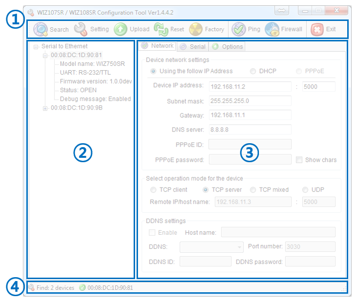
The following screen will appear once the program is installed and opened.
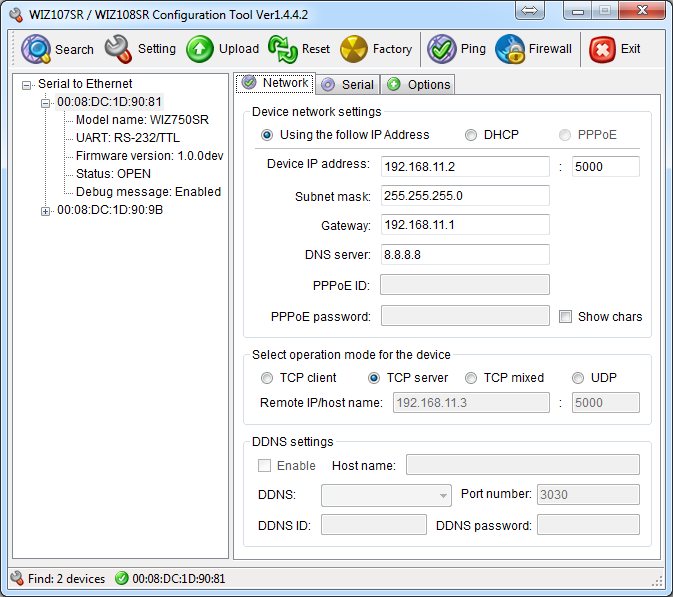 |
| Figure: Configuration Tool for WIZ750SR & WIZ107/108SR Products |
Configuration Tool Layout
 |
| Figure: Configuration Tool Layout |
The configuration tool is composed of four sections. Details of each section are available below.
1. Icon Menu
- Device search, save settings, device reset and Etc.
2. Device List
- Lists the information of searched devices on the network
3. Configuration Tab
- Check and modify settings
- Composed of three tabs: Network / Serial / Options
4. Progress Bar
- Shows the number of searched devices and the progress of firmware upload
Configuration Tool Details
1. Icon Menu
| Figure: Menu Icons |
-
Program is operated in Windows only.
-
If user has used either WIZ107/108SR, the same program can be used for WIZ750SR.
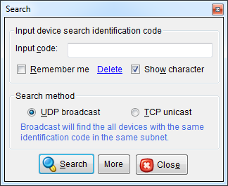
1) Device Search
- Searches for WIZ750SR on the same network.
- Search can be done via UDP Broadcast[1] or TCP Unicast[2]
- The UDP & TCP search pop-up windows is as below.
 | 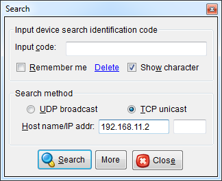 |
| Figure: UDP Search (broadcast) | Figure: TCP Search (unicast) |
- Use TCP/UDP port 50001 to search WIZ750SR. Search can be
unsuccessful due to firewall or virus protection software.
- In this case, try to search after turning off the firewall or virus protection software.
- Please refer to this guide if still unsuccessful.
2) Save Settings
- Save the settings for WIZ750SR.
- The settings will be applied through the configuration tool.
- Then the module will automatically reboot.
3) Firmware Upload
- Use the firmware binary file provided from WIZnet to update WIZ750SR’s firmware
- Then the module will automatically reboot.
- The following pop-up will appear once the firmware upload is complete.
 |
| Figure: Popup Message - Firmware Upload Successfully |
- Use TCP/UDP port 50002 to upload firmware on to WIZ750SR.
Firmware upload can be unsuccessful due to firewall or virus
protection software.
- In this case, try to upload after turning off the firewall or virus protection software.
- Please refer to this guide if still unsuccessful.
- The module will not work properly if the firmware is not correctly uploaded.
DO NOT TURN OFF POWER
DURING FIRMWARE UPLOADING
IT CAN CAUSE MALFUNCTIONING
-
UDP Broadcast Search: can search multiple devices
-
TCP Unicast Search: can search only one device
4) Device Reset
- Reboots WIZ750SR.
5) Factory Reset
- Returns the settings of WIZ750SR to factory default.
- Factory default setting of can be checked at WIZ750SR Factory Settings.
- Then the module will automatically reboot.
6) Ping Test
- Ping Test checks whether or not the module and PC can communicate with each other.
- If the module and PC can communicate via same network, the following ping reply will appear.
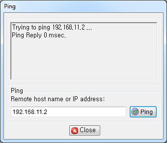 |
| Figure: Ping Request and Reply |
7) Firewall
- Opens the Windows control panel (firewall).
- Use this icon to turn off the firewall if either the device search or firmware upload is unsuccessful.
8) Exit
- Ends the configuration tool.
2. Device List
 |
| Figure: Device List |
-
List of devices searched will appears.
- Each device will be listed accordingly to each MAC addresses.
-
Users can check the below information by clicking the searched MAC address.
| Model name | Description |
|---|---|
| UART[1] | Shows the types of UART interfaces. - RS-232/TTL: WIZ750SR hardware TTL or RS-232 version. - RS-422/485: WIZ750SR hardware RS-422/485 version. |
| Firmware version | Shows the current firmware version[2] Composed of three sections: Major version number, Minor version number, and Maintenance version number ex) v1.0.0 |
| Status[3] | Shows the operational status of the device - BOOT: Settings and firmware upload is possible during this status - OPEN: Status before TCP connection - CONNECT: Status after TCP connection - UPGRADE: Firmware update or DHCP IP allocation during this status - ATMODE: Serial AT command mode. - UDP: UDP mode |
| Debug message | Shows the status of serial debug message The serial debug message is printed via separate Debug UART and not Data UART, and the interface connection setting is fixed as 115200-8-N-1:None |
-
Difference between WIZ107/108SR is the number of UART interfaces(1).
-
Stable version is recommended for usage. Ex) Development version: v1.0.0dev, Stable version: v1.0.0
-
Difference between WIZ107/108SR is the addition of BOOT and UDP mode.
3. Network Configuration Tab
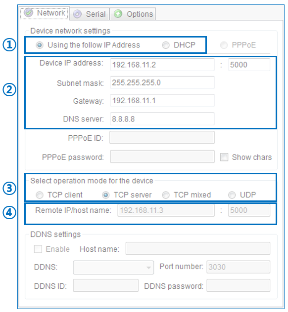 |
| Figure: Network Configuration Tab |
1) IP Address Allocation
-
Using the follow IP Address (default)
- By selecting this option, users can enter the IP address, port number, subnet mask, gateway address, DNS server into section 2.
-
DHCP
- By selecting this option, all information in section 2 is automatically allocated from the router (DHCP server).
* Details of IP address allocation are available at WIZ750SR User's Manual: IP address settings.
* PPPoE mode is not supported.
2) IP Address Setting Field
- WIZ750SR operates based on the allocated IP address from the
network.
- As explained above, users can enter the IP address, port number, subnet mask, gateway address, DNS server into section 2 if 'using the follow IP address' is selected.
3) Network Operation Mode
- Setting for the network operation mode.
- Users can choose among the four options that suits their application: TCP client mode, TCP server mode (default), TCP client/server mixed mode, UDP mode.
- Details of each network operation mode are available at WIZ750SR User's Manual: Network Operation Mode.
4) Remote Host Settings
- Users can enter the IP address or domain name of the destination or remote host when the module attempts connection in TCP client mode[1] or UDP mode.
- The port number of the destination is required.
- Details of the remote host setting are available at WIZ750SR User's Manual: Remote Host Settings.
* WIZ750SR does not support PPPoE / DDNS
4. Serial Configuration Tab
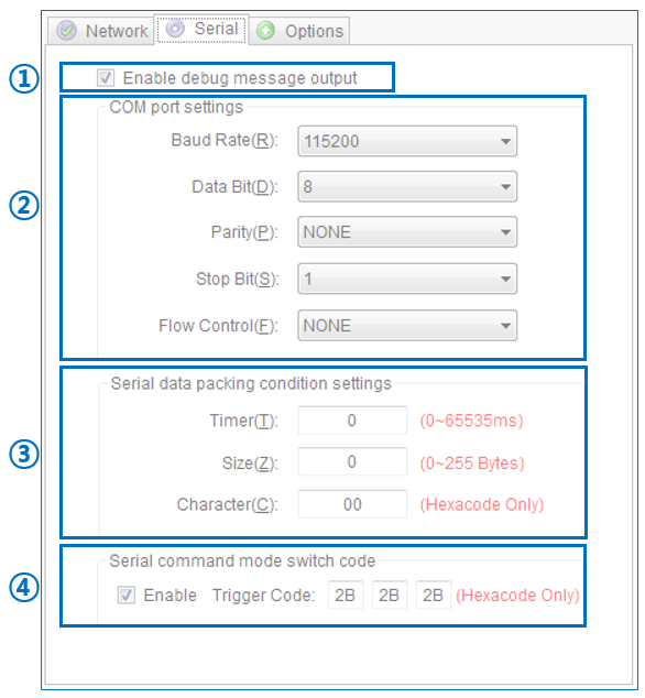 |
| Figure: Serial Configuration Tab |
1) Debug Message Enable
- Enable debug message output
- By enabling this option, the product information or error status can be printed via the Debug UART.
- The serial settings of the Debug UART is fixed as 115200-8-N-1:None.
- TCP client mode includes the TCP client mode of the TCP mixed mode.
2) Serial Port Settings
-
Baud Rate
- The supported baud rates are as below.
- 300, 600, 1200, 1800, 2400, 4800, 9600, 14400, 19200, 28800, 38400, 57600, 115200(default), 230400
-
Data Bit
- The supported data bits are as below.
- 7, 8(default)
-
Parity Bit
- The supported parity bits are as below.
- NONE(default), ODD, EVEN
-
Stop Bit
- The supported stop bits are as below.
- 1(default), 2
-
Flow Control
- RS-232/TTL versions support the below serial data flow control.
- NONE(default): Do not use flow control.
- XON/XOFF: Software flow control
- CTS/RTS: Hardware flow control
- RS-422/485 versions will operate as ‘NONE’ shown above no matter which option is selected.
- RS-232/TTL versions support the below serial data flow control.
3) Serial Data Option Settings
- WIZ750SR provides multiple serial data packing options[1]. By using this option, user command frame or all other data can be collected and sent together.
Data packing options can be
multi-selected but has priority as shown below.
Character => Size => Timer
-
Timer
- Range: 0 ~ 65535 / Unit: milliseconds (ms)
- Default: 0 (Not used)
- Collects the data until the designated time is lapsed and sent together.Will not operate if set to '0'.
- Range: 0 ~ 65535 / Unit: milliseconds (ms)
-
Size
- Range: 0 ~ 255 / Unit: data length (number of bytes)
- Default: 0 (Not used)
- Collects the data until the designated data length is reached and sent together.
- Will not operate if set to '0'.
- Range: 0 ~ 255 / Unit: data length (number of bytes)
-
Character
- Range & Unit: 1-byte character (Hex code)
- Default: 00 (Not used)
- Collects the data until the designated character is entered and sent together.
- The designated character will be included if the data size does not exceed the buffer size. The designated character will be excluded if the data size exceeds the buffer size.
- Will not operate if set to '0x00'.
- Range & Unit: 1-byte character (Hex code)
4) Serial Command Mode Switch Option Settings
-
Serial command mode switch code: Enable
- By enabling this option, the data communication mode (GW mode)
will change to serial command mode (AT mode) when sending the
command mode switch code via the serial data port.
- Default: Enabled
- Use the serial command mode composed of 2-byte to change settings.
- The existing TCP connection will be lost if the mode changes to serial command mode.
- By enabling this option, the data communication mode (GW mode)
will change to serial command mode (AT mode) when sending the
command mode switch code via the serial data port.
-
Serial command mode switch code: Trigger Code
- This is a 3-byte code for switching the mode from data mode to
serial command mode.
- Default: [2B][2B][2B] (+++)
- Each byte value reads hex code only.
- This is a 3-byte code for switching the mode from data mode to
serial command mode.
- Serial data can be collected according to the setting (character, size, or time) and be sent together.
Please take caution of the following when using Trigger code.
- It can only be recognized as switch code if there is a time gap of at least 500ms of no data communication time before and after the 3-byte command mode switch.
- The time interval for each byte of the 3-byte command mode switch code has to be at most 500ms.
- Do not end the command mode switch code[1] with CR((CR: Carriage return, ('\r', 0x0D) )) or LF((LF: Line feed, ('\n', 0x0A) )).
- The default interval of the time gap before and after the command mode switch code is 500ms. The operation is based on the timer value of the serial data packaging option.
5. Options Configuration Tab
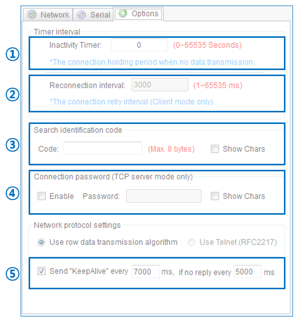 |
| Figure: Options Configuration Tab |
1) Inactivity Timer Settings
- Range: 0 ~ 65535 / Unit: seconds
- Default: 0 (Not used)
- If inactivity timer is set, connection is lost after the designated time without data communication is lapsed after the last data is sent.
- This setting is for TCP Server or TCP Client mode and mixed mode.
2) Re-connection Interval Settings
- Range: 1 ~ 65535 / Unit: milliseconds (ms)
- Default: 3000 (Use, 3 seconds)
- The re-connection interval is for TCP Client Operation, including TCP Client of the mixed mode.
- This option is requires in order to re-connect TCP communication in case it is lost.
- The setting must be at least 1ms.
3) Search Identification Code Settings
- Range: Up to 8-bytes string
- Default: Null (Not used)
- The search identification code is for identifying the device search[2].
- If this option is selected, the assigned code must be entered when searching devices.
|
| Figure: Search ID code (UDP broadcast search) |
4) Connection Password Settings
- Range: Up to 8-bytes string
- Default: Null (Not used)
- Connection password is available for TCP server mode (including TCP server mode of the mixed mode).
- TCP client must send the connection password character upon connecting to WIZ750SR in order for data communication.
- TCP connection will be disconnected if the password does not match
-
The serial command after switching modes must end with CR and LF.
-
In cases when there are multiple devices in the same network.
5) TCP Keep-Alive Settings
-
Send Keep-Alive: Enable
- This option allows the connection status to be kept alive by
sending the ‘keep-alive packet’ in all three TCP modes. (TCP
server, TCP client, and TCP mixed mode)
- Default: Enabled (recommended)
- TCP connection is disconnected if there is no response to the ‘keep-alive’ packet. (Socket close / disconnect)
- The ‘keep-alive’ packet is sent after the Ethernet packet is sent at least once from WIZ750SR.
- This option allows the connection status to be kept alive by
sending the ‘keep-alive packet’ in all three TCP modes. (TCP
server, TCP client, and TCP mixed mode)
-
Send Keep-Alive Interval
- Range: 0 ~ 65535, Unit: milliseconds(ms)
- Default: 7000, 5000 (recommended, 7 seconds / 5 seconds)
- The required interval for sending the ‘keep alive’ packet is as
below.
- The time until the first ‘keep-alive’ packet is sent
- The time interval between each ‘keep-alive’ packets
- Range: 0 ~ 65535, Unit: milliseconds(ms)
-
This option is recommended in case of a physical disconnection with the remote device.
- This options is recommended especially in TCP server mode.
6. Progress Bar
| Device Search | |
|---|---|
| Firmware Upload | |
| Figures: Progress Bar |
- Shows the result of search.
- MAC addresses will be shown together if multiple devices are searched.
- The progress bar is shown during firmware updates.
If there is any problem?
Please refer to our Troubleshooting Guide!
Navigation
WIZ750SR
WIZ750SR series Downloads