Getting Started-[EN]
Supported Languages

This section was written on the assumption that the use of WIZ750SR-100-EVB evaluation board.
Unpacking the WIZ750SR-100
What's in the Box?
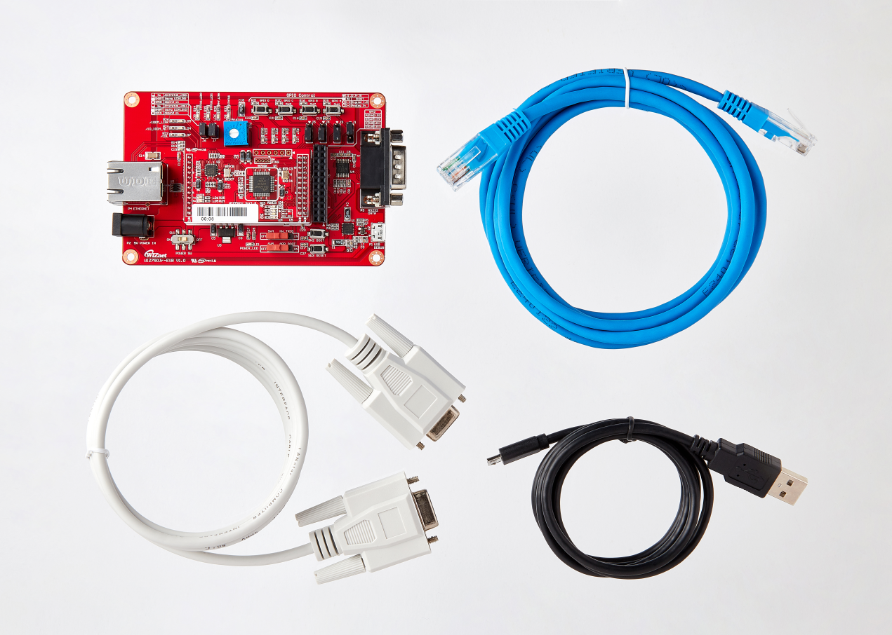 |
| Figure: WIZ750SR-100 Rev. 1.0 Evaluation Board Package |
The WIZ750SR-100 evaluation board package contains the following parts.
- WIZ750SR-100 TTL Module
- WIZ750SR-100-EVB Evaluation Board
- Cables (Ethernet / Serial / Micro USB Type B)
The entire list of parts of the board is available at the WIZ750SR-100 Overview: Product Contents page.
Device Layout
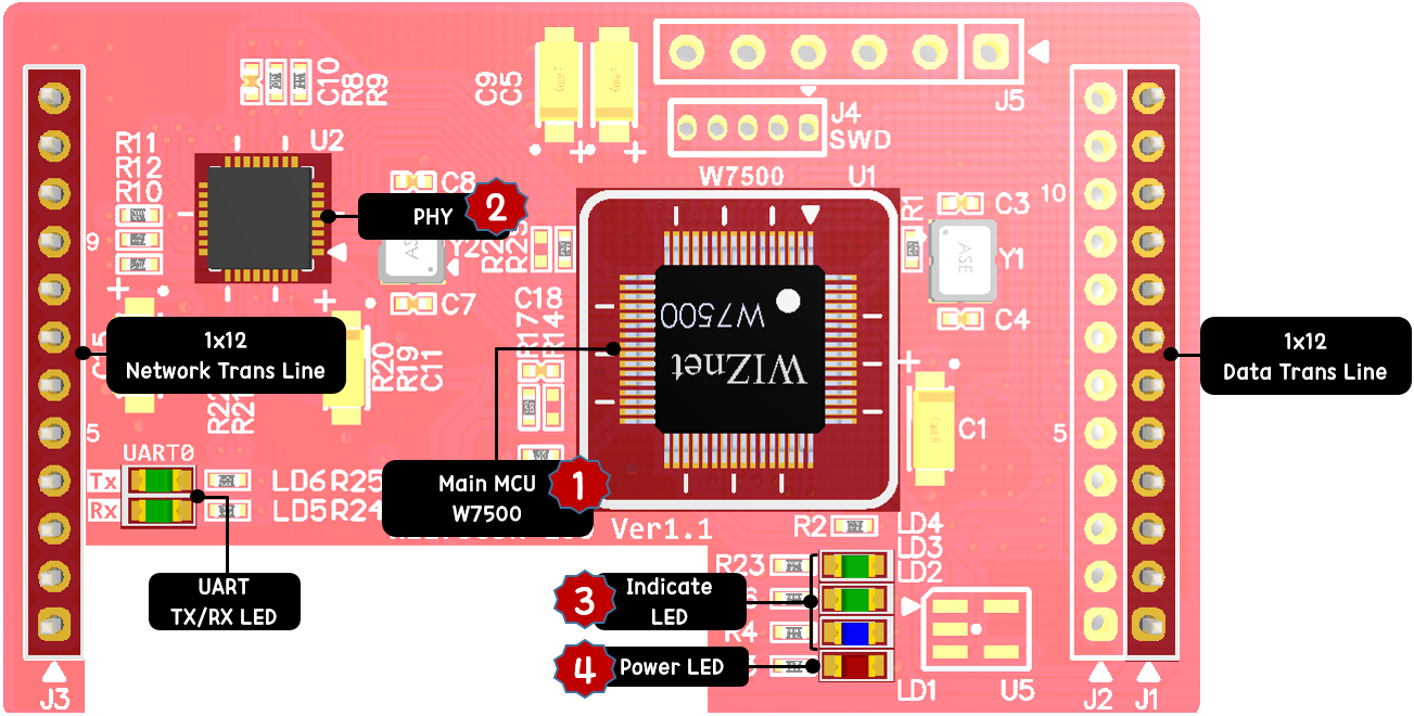 |
| Figure: WIZ750SR-100 Revision 1.1 Top |
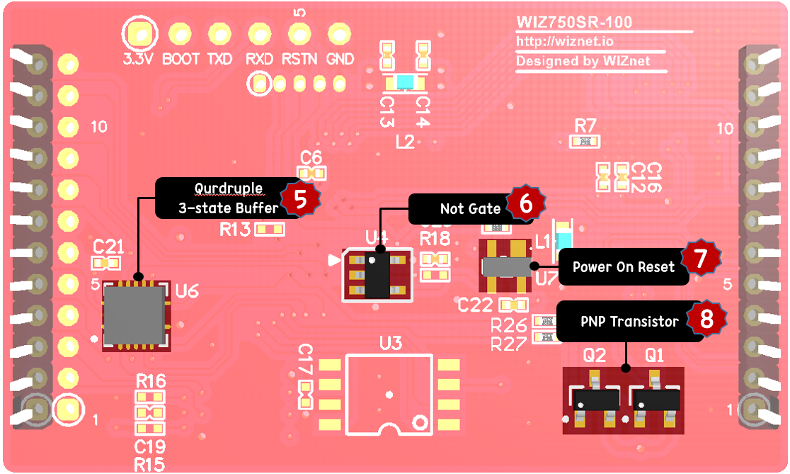 |
| Figure: WIZ750SR-100 Revision 1.1 Bottom |
Parts
-
ARM Cortex-M0 based Hardwired TCP/IP core plus PHY Ethernet MCU W7500 [1] [1]
-
PHY(Single 10/100M Ethernet Transceiver) [2]
-
Indicate LED (blue: PHY link status / green: TCP connection status) [3]
-
Power LED(red) [4]
-
Buffer IC for UART signal [5]
-
Not gate WIZ750SR-100 reset is Active high [6]
-
Power on reset for improvements of Reset function stability [7]
-
PNP Transistor for UART trans/receive indicate [8]
-
EEPROM for saving device setting: It is Not mounted
-
Data Flash for saving device data: It is Not mounted
Interfaces and Ports
- Data UART Port: 1x12 2.00mm Pin header
- Network Port: 1x12 2.00mm Pin header
- User's Optional Port: 1x12 2.00mm Pin header (Debug UART pins and MCU boot pin / 4-Pins user I/O and application boot pin / GND)
Prerequisites for Setup
Software
- Configuration tool program (Download page)
- TCP server / TCP client / UDP terminal program
- Serial terminal program
Hardware
- Your WIZ750SR-100 module and Evaluation board
- Ethernet cable
- USB type B cable (for Debug UART)
- DB9 serial RS-232 cable (for Data UART, RS-232/TTL Ver. only)
- Power source for device
- Such as 5V DC adapter, USB port on your computer, or 3.3V Power source
Connect Your WIZ750SR-100
WIZ750SR-100 Factory Settings
| Network Settings | Local | IP address | 192.168.11.2 | - |
|---|---|---|---|---|
| ::: | ::: | Gateway address | 192.168.11.1 | - |
| ::: | ::: | Subnet mask | 255.255.255.0 | - |
| ::: | ::: | DNS server | 8.8.8.8 | Google Public DNS |
| ::: | ::: | Port number | 5000 | - |
| ::: | Remote | IP address | 192.168.11.3 | - |
| ::: | ::: | Port number | 5000 | - |
| Serial Port Settings | Data UART | 115200-8-N-1 / Flow Control: None | - |
|---|---|---|---|
| ::: | Debug UART | 115200-8-N-1 / Flow Control: None | Fixed |
| User's I/O Settings | UserIO A | Analog / Input | Read only |
|---|---|---|---|
| ::: | UserIO B | Digital / Input | Read only |
| ::: | UserIO C | Digital / Output | Read / Write |
| ::: | UserIO D | Digital / Output | Read / Write |
-
Operation mode: TCP server mode
-
Debug message: Enabled
-
Serial command mode switch: Enabled
-
Serial command mode switch code: +++ (hex code, [2B][2B][2B])
-
Data packing option - Time: Disabled
-
Data packing option - Size: Disabled
-
Data packing option - Char: Disabled
-
Inactivity Timer: Disabled
-
Reconnection Timer: 3 second
-
Keep-Alive: Enabled, 7-sec initial delay, 5-sec send interval
PC Settings
Double check that the WIZ750SR-100 and the PC, or laptop you are using to set up WIZ750SR-100 with are both on the same Ethernet network.
Example: PC Network Settings
* When the WIZ750SR-100's settings are factory default,
| Network Settings | PC or laptop (= Remote) | IP address | 192.168.11.3 | - |
|---|---|---|---|---|
| ::: | ::: | Gateway address | 192.168.11.1 | - |
| ::: | ::: | Subnet mask | 255.255.255.0 | - |
| ::: | ::: | Port number | 5000 | - |
-
User should to matching the network settings of 'WIZ750SR-100's remote host' and 'PC (or laptop)' for testing TCP client/mixed mode.
-
If the DHCP(automatic IP allocation) is used, both the WIZ750SR-100 and test PC must be set to be assigned the same IP from the same router.
Connecting Steps
The WIZ750SR-100-EVB is designed to use the DB9 connector to connect with the user’s serial device. Therefore, it is recommended to have all Ethernet and serial ports connected to the PC when testing. If the PC does not have a serial port, please purchase a RS-232 to USB converter separately.
Step 1: Plug in
Connect the WIZ750SR-100 module to evaluation board and also the cable as shown in the picture below.
-
Ethernet Cable
- Used to connect the evaluation board’s RJ-45 connector and the PC’s Ethernet network interface card (PC's RJ-45 connector)
-
Serial Cable
- Used to connect the evaluation board’s DB9 connector and the serial interface card (DB9 connector). If the PC does support serial interface, use the RS-232 to USB converter.
-
Optional: USB type B cable (for debug message)
- Used to connect the evaluation board’s USB connector and the PC’s USB connector.
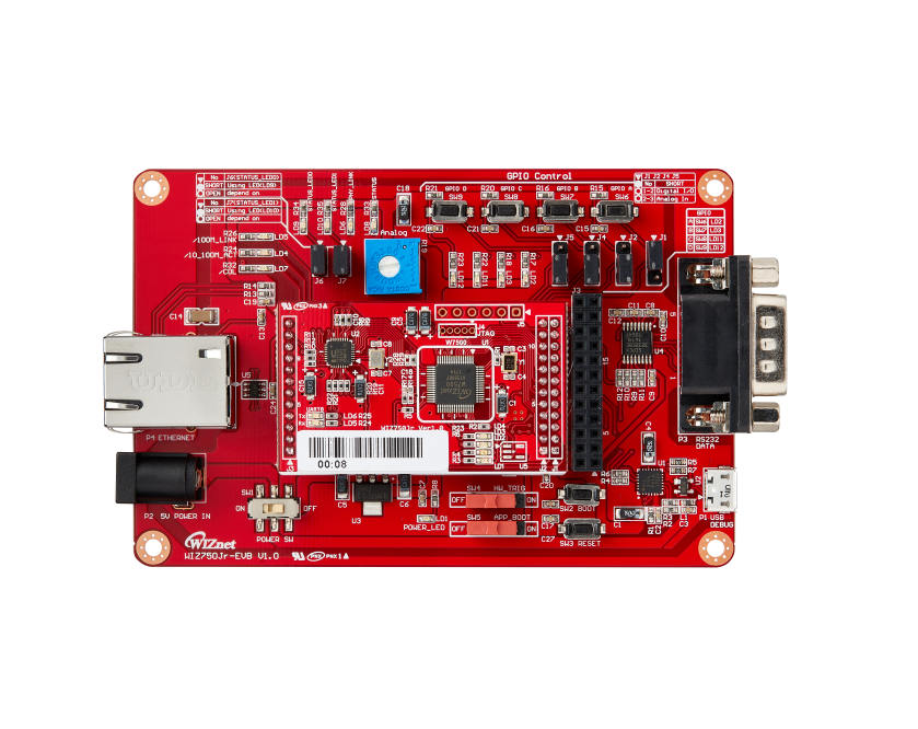 |
| Figure: Combining WIZ750SR-100 module and EVB |
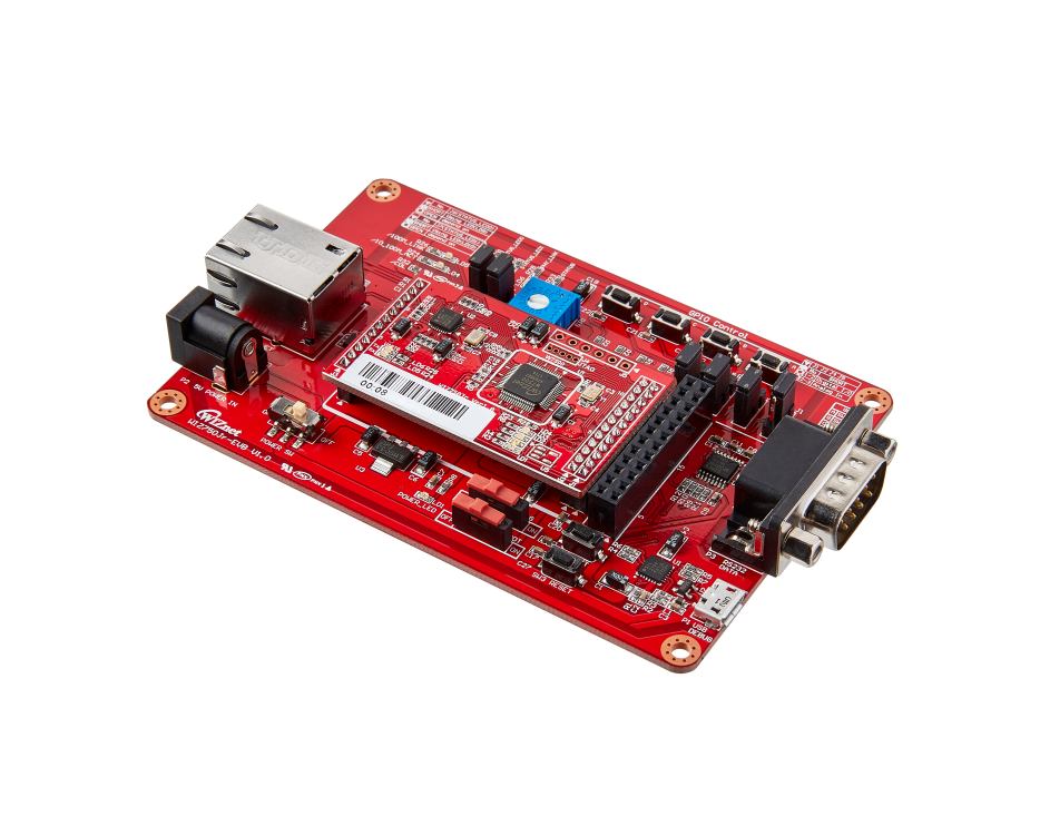 |
| Figure: WIZ750SR-100-EVB side view |
Step 2: Power on
Connect the 5V power adaptor or USB cable to the evaluation board and turn on the power switch.
- The power LED will turn red once the evaluation board is on.
Step 3: Search
Open the configuration tool and click the search button. If the board is turned on and connected to the same network, the MAC address or settings of the WIZ750SR-100 module can be checked using the configuration tool.
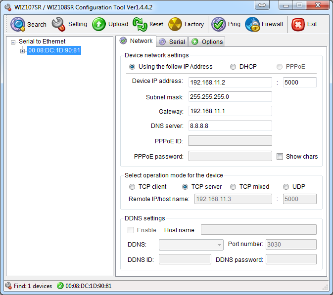 |
| Figure: WIZnet Configuration Tool |
Step 4: Set up your WIZ750SR-100
Change the settings accordingly to the customer’s environment. The test shown in this document is based on factory setting.
* Click the **setting** button to apply the changes in settings of the configuration tool.
Step 5: Connect
Connect the PC as the TCP client of the user’s serial device for data communication testing. In order to do this, the serial terminal program / TCP client terminal program must be opened on the PC. The serial terminal program and TCP client program must be set as below.
- Serial terminal program: 115200-8-N-1, Flow control: None
- TCP client program: 192.168.11.2:5000 (The IP address and port number of WIZ750SR-100)
The COM port for serial terminal program connection can be checked as below.
- Control Panel > System > Device Manager
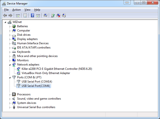 |
| Figure: Device Manager |
Step 6: Verify
The basic data communication of the WIZ750SR-100 can be verified as below.
-
Serial to Ethernet: data communication verification
- Enter the character string in the serial terminal and check if the identical character string appears on the TCP client terminal.
-
Ethernet to Serial: data communication verification
- Enter the character string in the TCP client terminal and check if the identical character string appears on the serial terminal.
Step 7: Done
Now you’re ready to use the WIZ750SR-100!
-
This document is based on the assumption of the PC as the serial device / remote network device.
-
The next step is to connect the WIZ750SR-100 module to the target serial device and check if the device can communicate, control, and monitor via the remote PC or monitoring server.
If there is any problem?
Please refer to our Troubleshooting Guide!
Navigation
WIZ750SR series Common Documents
WIZ750SR series Downloads