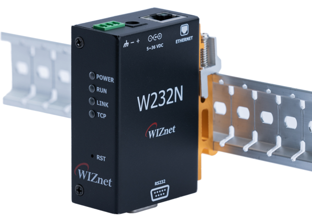
This document is the HW specification for the W232N, an industrial Ethernet to RS232 data conversion device.
- RS232 to Ethernet protocol conversion device
- Support multiple protocols
- TCP Server
- TCP Client
- SSL TCP Client
- TCP Mixed
- Modbus RTU/ASCII (available only in TCP Server mode)
- UDP
- MQTT Client
- MQTTS Client
- Support custom protocols (Please submit custom protocol requests via this link.)
- HTTP
- HTTPS
- CoAP
- External device OTA
- Enables easy implementation of Ethernet into existing serial devices
- KC,FCC certified to ensure high system stability and reliability
- Supports 10/100Mbps Ethernet and up to 230kbps serial speeds
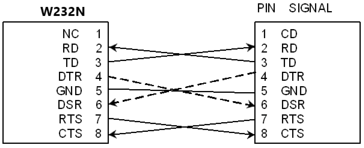
- Supports RS232C standard with D-SUB9 port
- Supports password setting for device discovery
- Supports AT command via D-SUB9 port
- Configurable with Config-tool
- Supports Web Config
- Wide input voltage 5~36V
- Industrial-standard operating temperature -25~80°C
- Supports DIN rail (DIN 46277) mounting
- Protected against ESD
The package of W232N is organized as follows.
|
|---|
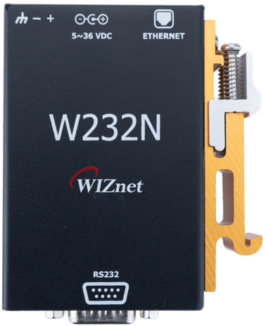 |
| W232N Revision 1.0 Front |
|
|---|
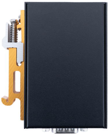 |
| W232N Revision 1.0 Back |
|
|---|
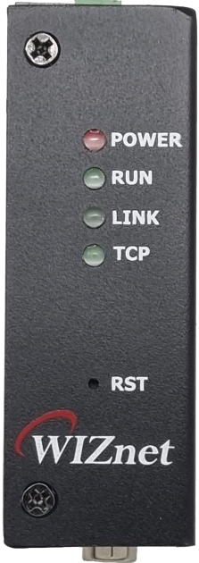 |
| W232N Revision 1.0 LED |
|
|---|
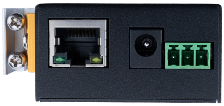 |
| W232N Revision 1.0 RJ45,power jack |
|
|---|
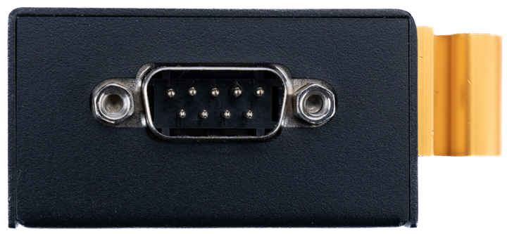 |
| W232N Revision 1.0 DSUB |
|
|---|
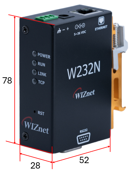 |
| W232N Revision 1.0 Dimension |
|
|---|
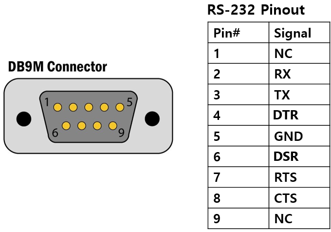 |
| W232N Revision 1.0 DB9M port |
| Pin Number | Signal | Description |
|---|
| 1 | DCD | NC |
| 2 | RXD | Receive Data |
| 3 | TXD | Transmit Data |
| 4 | DTR | Data Terminal Ready |
| 5 | GND | System Ground(Signal Ground) |
| 6 | DSR | Data Set Ready |
| 7 | RTS | Request To Send |
| 8 | CTS | Clear To Send |
| 9 | RI | NC |
|
|---|
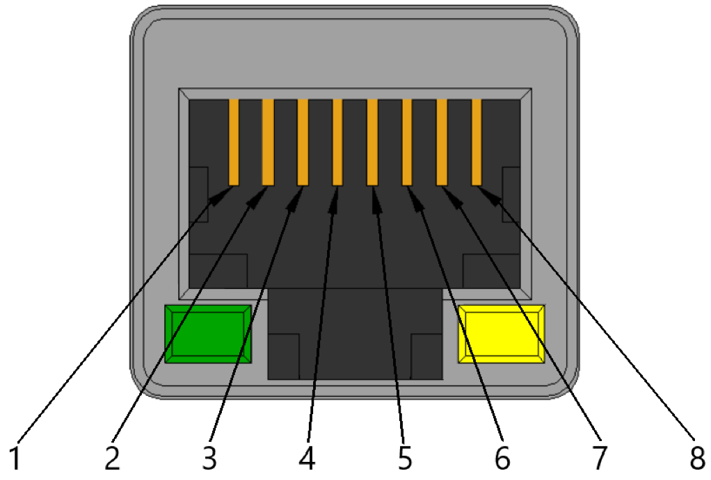 |
| W232N Revision 1.0 RJ45 port |
| Pin Number | Signal | Description |
|---|
| 1 | TXP | TX+ |
| 2 | TXN | TX- |
| 3 | RXP | RX+ |
| 4 | NC | PoE+ or PoE- |
| 5 | NC | PoE+ or PoE- |
| 6 | RXN | RX- |
| 7 | NC | PoE- or PoE+ |
| 8 | NC | PoE- or PoE+ |
- PoE is only available on models that support it.
- When using PoE, the polarity of pins 4,5 and 7,8 must be different.
- If pin 4,5 is +, then pin 7,8 is -, or if pin 4,5 is -, then pin 7,8 is +.
|
|---|
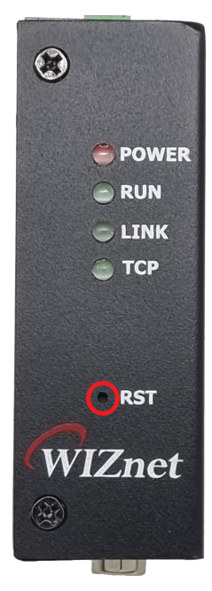 |
| W232N Revision 1.0 Reset SW |
- The top case can be removed by removing the bolts (M3) on each side of the W232N.
|
|---|
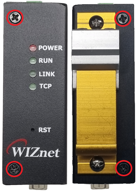 |
| W232N Case bolts |
|
|---|
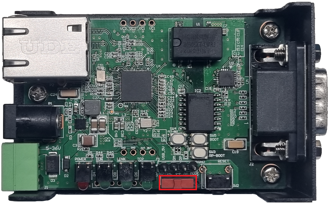 |
| AT Mode SW |
- You can use an AT Morse switch to enter serial command mode.
For more information, see How to use the AT command in the Manual below.
|
|---|
 |
| Factory Reset SW |
- You can use the factory reset switch to factory reset your device.
For detailed instructions, see the Factory Reset guide in the Manual below.
|
|---|
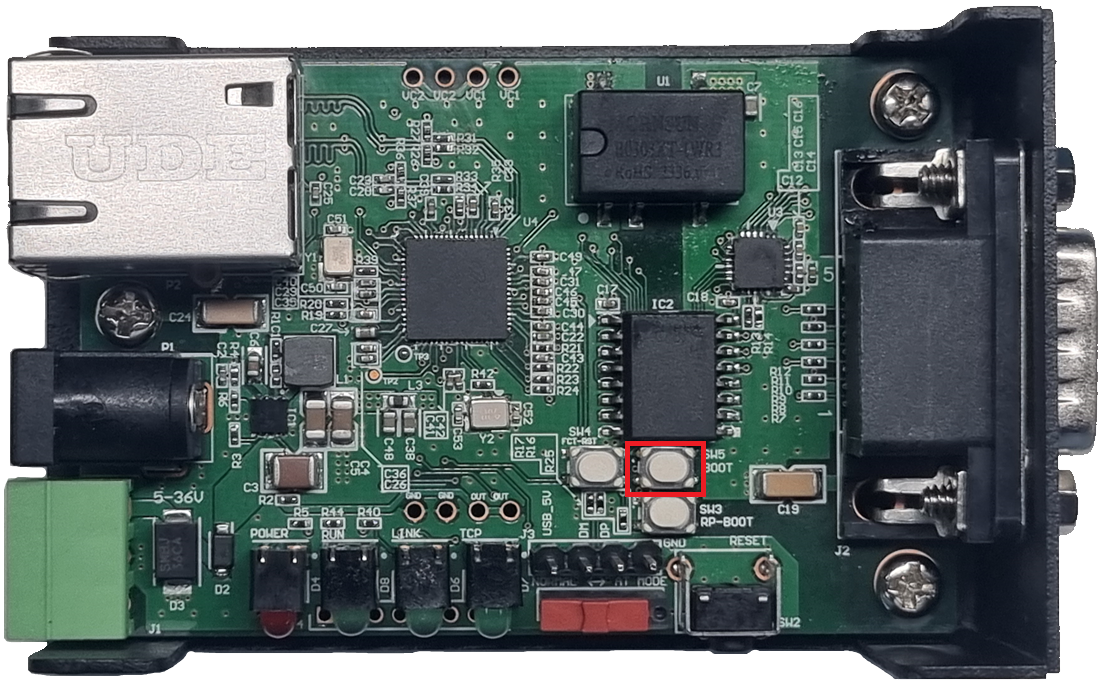 |
| Boot SW |
|
|---|
 |
| W55RP20 Boot SW |
|
|---|
 |
| USB Header |
-The USB header is used to upload and update the FW after the W55RP20 enters BOOT mode.
For detailed instructions, see the FW update guide in the Manual below.
The W232N can be powered via a DC jack, terminal block, or RJ45 jack if the product is PoE-enabled.
The available voltage is 5 V to 36 V.
If the polarity is reversed when power is applied, a protection circuit will prevent the power from being turned on.
|
|---|
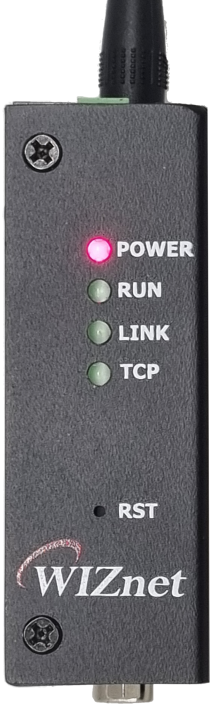 |
| Power LED |
During normal operation, the POWER LED will be solid red and the RUN LED will flash in 1-second cycles, confirming that the W232N's FW has booted successfully.
This document is a web server configuration guide for the W232N, an industrial Ethernet to RS232 data conversion device.
- Web Server Config Supported Devices List
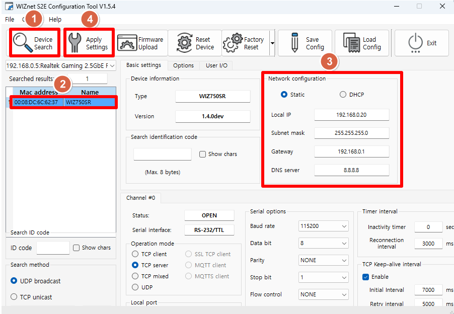
After connecting the power and Ethernet cables to the W232N, run the Configuration Tool you downloaded from the 'Software' section above. Then, click the buttons in the order shown in the picture below to set the IP range to the same as the user's PC.
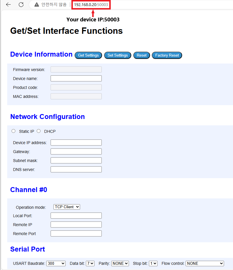
Using a web browser (e.g., Chrome), connect to the web server at port 50003 of the S2E module address you have configured.
|
(1) Get W232N information
|
|---|
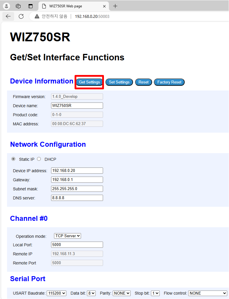 |
| Figure: Click the "Get Settings" button to load the information from the W232N |
(2) Description of Fields
|
|---|
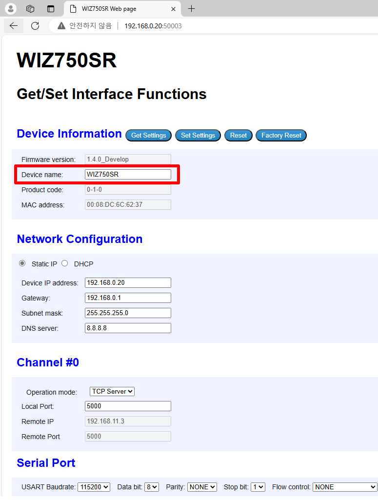 |
| Figure: Device Name Field |
|
|---|
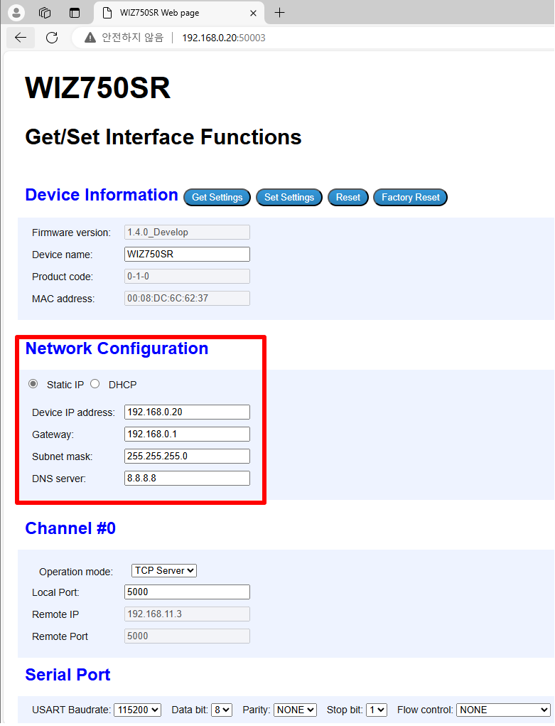 |
| Figure: Network Information Field for W232N |
|
|---|
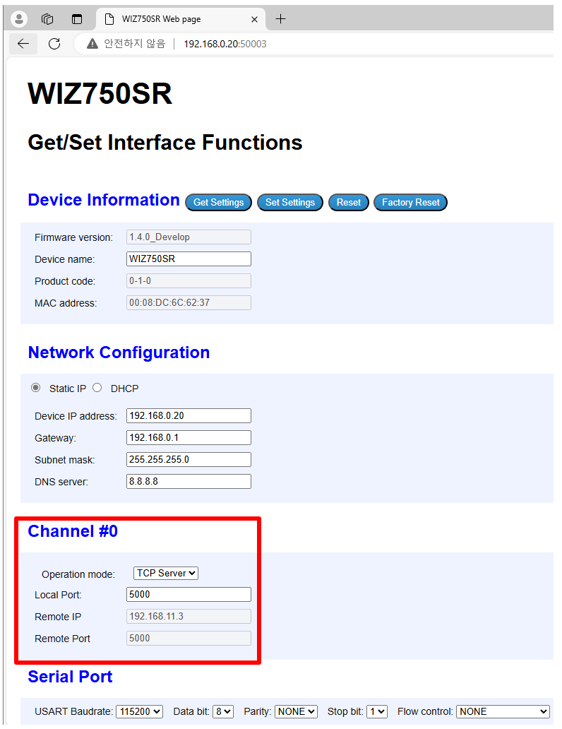 |
| Figure: Operation Mode and Port Field for W232N |
|
|---|
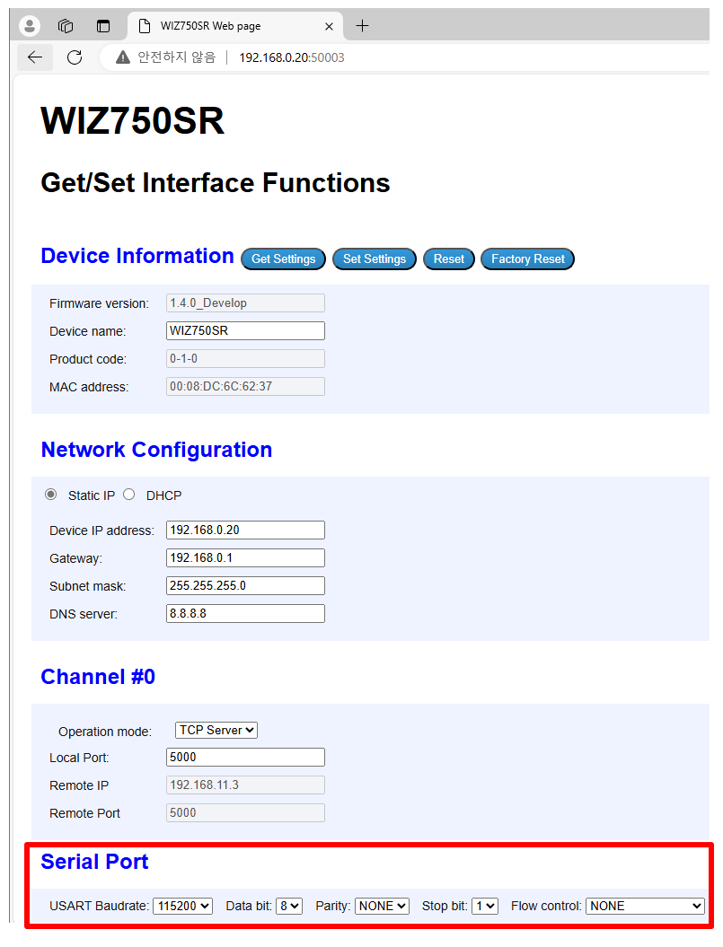 |
| Figure: UART Field for W232N |
(3) Set W232N information
|
|---|
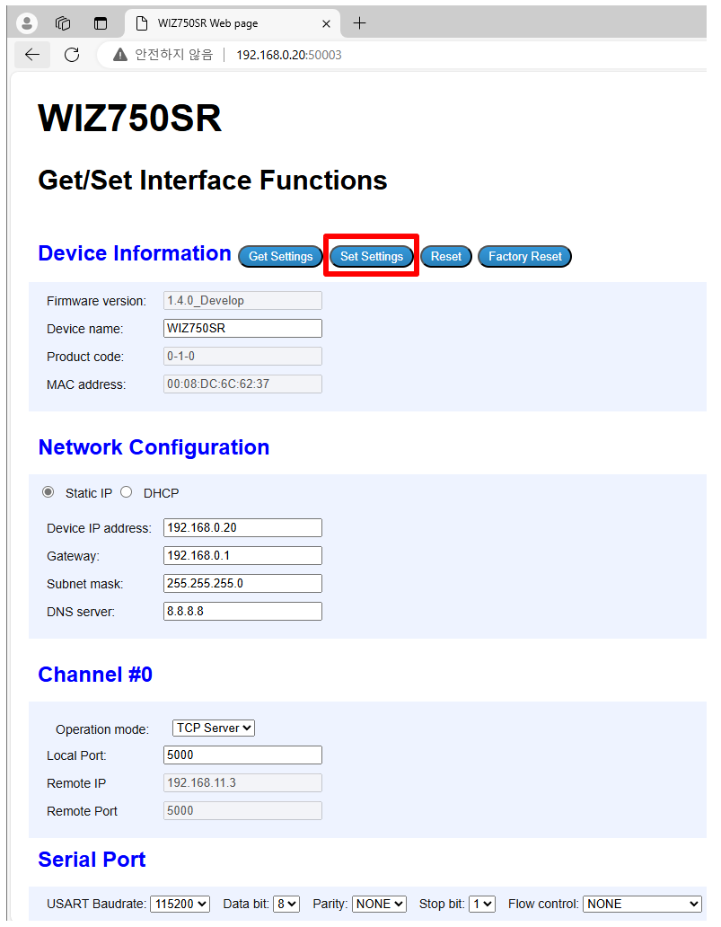 |
| Figure: Click "Set Settings" and save the updated information for the W232N |
| H/W version | Filetype | Download Link | Remarks |
|---|
| 1.0 | Step |  Download Download | - |