Reading the analog value using a variable resistor
Outline
This is an exercise to read Analog values made by variable resistor (potentiometer). The ADC (Analog Digital Converter) module of W7500 chip embedded in WIZwiki board is used. User can learn how to read sensor's analog output data.
What you need
- WIZwiki-W7500
- USB cable
- Breadboard
- Jumper wire
- Rotary Potentiometer (10K Ohm)
Hardware
The Circuit
This is the circuit for this example.
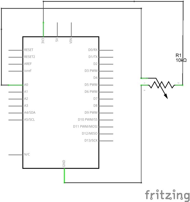
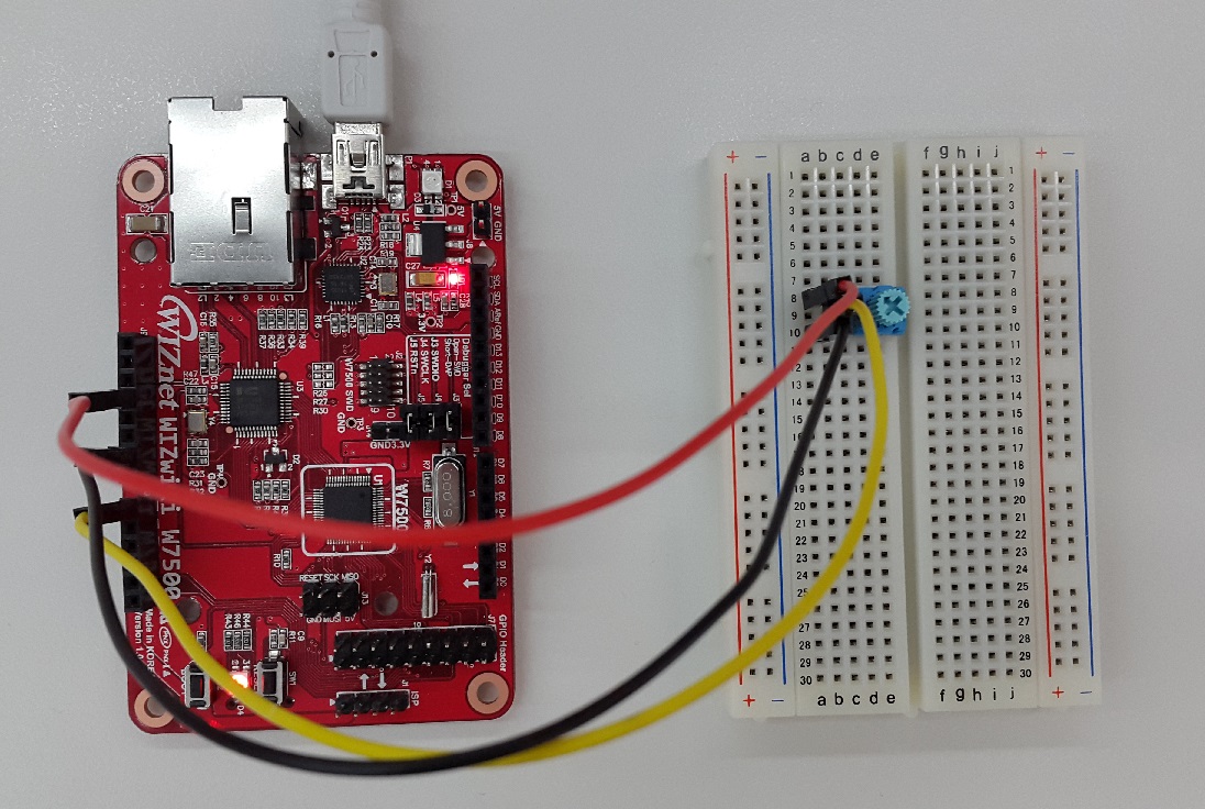
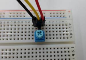
Connections

Software
Example Code
Below are the example codes. Delete the default code and copy/paste the codes below and compile.
#include "mbed.h"

AnalogIn analog_value(A0);

DigitalOut led(LED1);

int main(/) {
    float meas;

    printf("\nAnalogIn example\n");

    while(1) {
        meas = analog_value.read(/); // Converts and read the analog input value (value from 0.0 to 1.0)
        meas = meas * 3300; // Change the value to be in the 0 to 3300 range
        printf("measure = %.0f mV\n", meas);
        if (meas > 2000) { // If the value is greater than 2V then switch the LED on
          led = 0;
        }
        else {
          led = 1;
        }
        wait(0.2); // 200 ms
    }
}
How to run and test result
When you download the compiled binary to the WIZwiki board and push the reset button, check the serial port message as rotating the dial of potentiometer. You can see the measured value (mV unit) periodically.
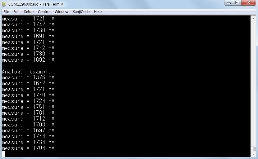
If user rotates the dial clock-wise, the measured value will increase. If the measured value is above than 2000mV, then the LED1 of WIZwiki board turns on. If the measured value is less than 2000mV, then the LED1 turns off.
The WIZwiki board can read analog values from external circuit and convert them to digital values.
Learning Resources
🌎Potentiometer, from wikipedia
🌎Analog-to-digital converter, from wikipedia