Blinking LED with a switch
Outline
This is an exercise to blink an LED with a switch. Users can learn how to put digital input into the WIZwiki board with a switch. Users can learn how to get digital output from a specified pin in the WIZwiki board.
What you need
- WIZwiki-W7500
- USB cable
- Breadboard
- Jumper wire
- Switch
- LED
- Resistor (330 Ohm)
- Test S/W : In order to check serial data, terminal program is required on the PC. Tera Term is used in this exercise.
Hardware
The Circuit
This is the circuit for this example. 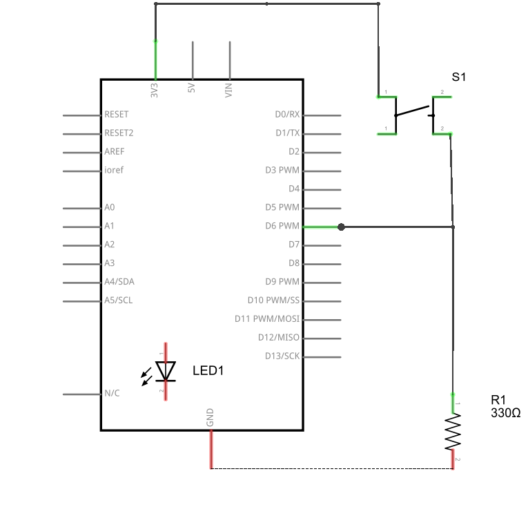
The LED for this example is placed on the WIZwiki board and it is shown
in the red box in the cicuit below. 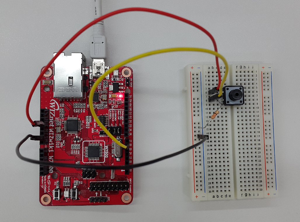
Connections
Software
Example Code
Below are the example codes. Delete the default code and copy/paste the codes below and compile.
#include "mbed.h"

DigitalOut myled(LED1);
DigitalIn mybutton(D6);

int main(/) {
    while(1) {
        if (mybutton == 1)
          myled = 0;
        else
          myled = 1;
    }
}
How to run and test result
DigitalOut myled(LED1) part configures LED1 as an output mode. DigitalIn mybutton(D6) part configures D6 pin as an input mode.
When pushing a button, the LED turns on. When 3.3V drives to D6 pin, mybutton will be recognized as “1”, myled becomes “0”. When myled becomes “0”, then the LED1 on the WIZwiki board turns on.
When you release the button, the LED turns off.
To learn Class and API like the DigitalOut and DigitalIn parts of the above example code, refer to the mbed Handbook page. 🌎https://os.mbed.com/handbook/Homepage