WIZ550io
WIZ550io
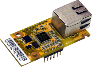
The WIZ550io is an auto-configurable Ethernet module integrating the W5500 hardwired TCP/IP chip with an embedded PHY, transformer, and RJ45 (MAGJACK). It automatically assigns network parameters using a pre-programmed MAC address, enabling instant network access upon power-up. Designed for easy and rapid Ethernet connectivity, it eliminates the need for manual MAC/IP configuration.
Pin Information
- All Pins
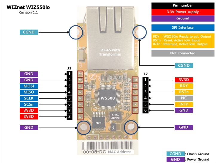
J1 — SPI & Power
| Pin | Type | Name | Description |
|---|---|---|---|
| 1 | P | GND | Ground |
| 2 | P | GND | Ground |
| 3 | I | MOSI | SPI Master-Out / Slave-In |
| 4 | O | MISO | SPI Master-In / Slave-Out |
| 5 | I | SCLK | SPI clock input |
| 6 | I | SCSn | SPI chip select (active low) |
| 7 | P | 3V3D | 3.3 V power |
| 8 | P | 3V3D | 3.3 V power |
J2 — Control & Status
| Pin | Type | Name | Description |
|---|---|---|---|
| 1 | P | 3V3D | 3.3 V power |
| 2 | O | RDY | Low during auto-config, high when ready |
| 3 | I | RSTn | Hardware reset (active low, ≥ 500 µs) |
| 4 | I | NC | Not connected |
| 5 | O | INTn | Interrupt output (low-active, cleared via IR/Sn_IR) |
| 6 | P | GND | Ground |
Software reset clears configuration (MAC/IP) inside the W5500.
Always use hardware reset (RSTn) for proper reinitialization.
If software reset is necessary, store and restore MAC and network settings manually.
Features
- Auto network configuration with factory-assigned MAC address
- Integrated transformer and RJ45 (MAGJACK)
- Built-in W5500 TCP/IP offload engine
- SPI interface for host communication
- Power-down and Wake-on-LAN (WoL) support
- Default network setup
- IP: 192.168.1.2
- Subnet: 255.255.255.0
- Gateway: 192.168.1.1
- Dimensions: 54 × 26 × 24 mm (± 0.5 mm)
Version / History
| Version | Date | Description |
|---|---|---|
| 1.0 | 2013-08-01 | Initial release |
| 1.1 | 2014-01-17 | Changed external transformer + RJ-45 to integrated MAGJACK |
| 1.2 | 2015-04-20 | Added 33 Ω resistor on MDI line to reduce EMI; PCB migrated (PADS → Altium) |
| 1.3 | 2018-08-10 | Modified internal 3V3D copper area for improved ESD performance |
Electrical Characteristics
- DC Characteristics
- Power Dissipation
| Symbol | Parameter | Pins | Min | Typ | Max | Unit |
|---|---|---|---|---|---|---|
| VDD | Supply voltage | 3.3 V | 2.97 | 3.3 | 3.63 | V |
| VIH | High-level input | ALL | 0.7×Vcc | – | 5.5 | V |
| VIL | Low-level input | ALL | –0.3 | – | 0.3×Vcc | V |
| VOH | High-level output | ALL | 2.9 | 3.3 | – | V |
| VOL | Low-level output | ALL | 0.0 | – | 0.52 | V |
| IDD | Supply current (Normal) | 3.3 V | – | 141 | – | mA |
| IPD | Supply current (Power-down) | 3.3 V | – | 13 | – | mA |
| Condition | Min | Typ | Max | Unit |
|---|---|---|---|---|
| 100 Mb/s Link | – | 135 | – | mA |
| 10 Mb/s Link | – | 80 | – | mA |
| Unlink (Auto-negotiation) | 62 | – | 75 | mA |
| 100 Mb/s Tx | 137 | – | 141 | mA |
| 10 Mb/s Tx | – | 83 | – | mA |
| Power-down | – | 13 | – | mA |
Documentation
This section provides key documentation, including user manuals and datasheets, to help you understand product features, specifications, and usage.
| Title | Description | Link | Notes |
|---|---|---|---|
| Datasheet | Technical specifications and features of the W5500 chip | - |
SPI operation of W5500-io follows one of W5500. For more information about SPI operation of W5500-io, please refer to W5500 Datasheet.
Software Resources
- Driver
- Application Note
Driver
| Resource | Description |
|---|---|
| Official WIZnet driver library for W5500 and other chips |
The ioLibrary_Driver is an MCU-independent library for WIZnet W5x00, W6x00 chips .
It provides implementations of essential TCP/IP services, enabling developers to build network applications with minimal MCU dependencies.
Supported services
DHCP, DNS, MQTT, SNTP, TFTP, HTTP Server
Application Note
| Example Name | Description | Notes |
|---|---|---|
| How to use TCP Function | ITCP Function handles IPv4 layer communication | |
| How to use UDP Function | UDP Function handles IPv4 layer communication | |
| How to use IPRAW Mode | IPRAW Mode handles IPv4 layer communication | |
| How to use PPP/PPPoE | PPP is Link-Layer protocol for point-to-point |
These application notes explain how to use W5500's core networking functions including TCP, UDP, IPRAW mode, and PPPoE protocols.
It will make WIZ550io hang up due to clearance of all information in the registers of W5500. A tiny MCU inside WIZ550io initializes W5500 with embedded MAC address and a default IP address and Initialization is triggered by RSTn.* In case of SW reset, all registers in W5500 will be cleared and WIZ550io will not initialize itself. All information inside WIZ550io will be lost and WIZ550io will hang up instead. Therefore, we recommend HW reset instead of SW reset. Nevertheless, if users want to use SW reset, we recommend to save MAC address and network information including IP address, Subnet mask and Gateway address before SW reset, and writing those information to WIZ550io after SW reset.
Hardware Resources
| Title | Revision | Description | Download | Notes |
|---|---|---|---|---|
| schematic | 1.0 - 1.2 | Circuit diagram for hardware design reference | Revision 1.0 – 1.3 share same schematic format; 1.3 improved ESD by internal copper modification | |
| PCB layout | 1.2 / 1.3 | PCB design source for Altium | — | |
| Part list | 1.0 – 1.2 | List of components used in the hardware | — | |
| 3D File | 1.3 | 3D model for mechanical design and visualization | — |
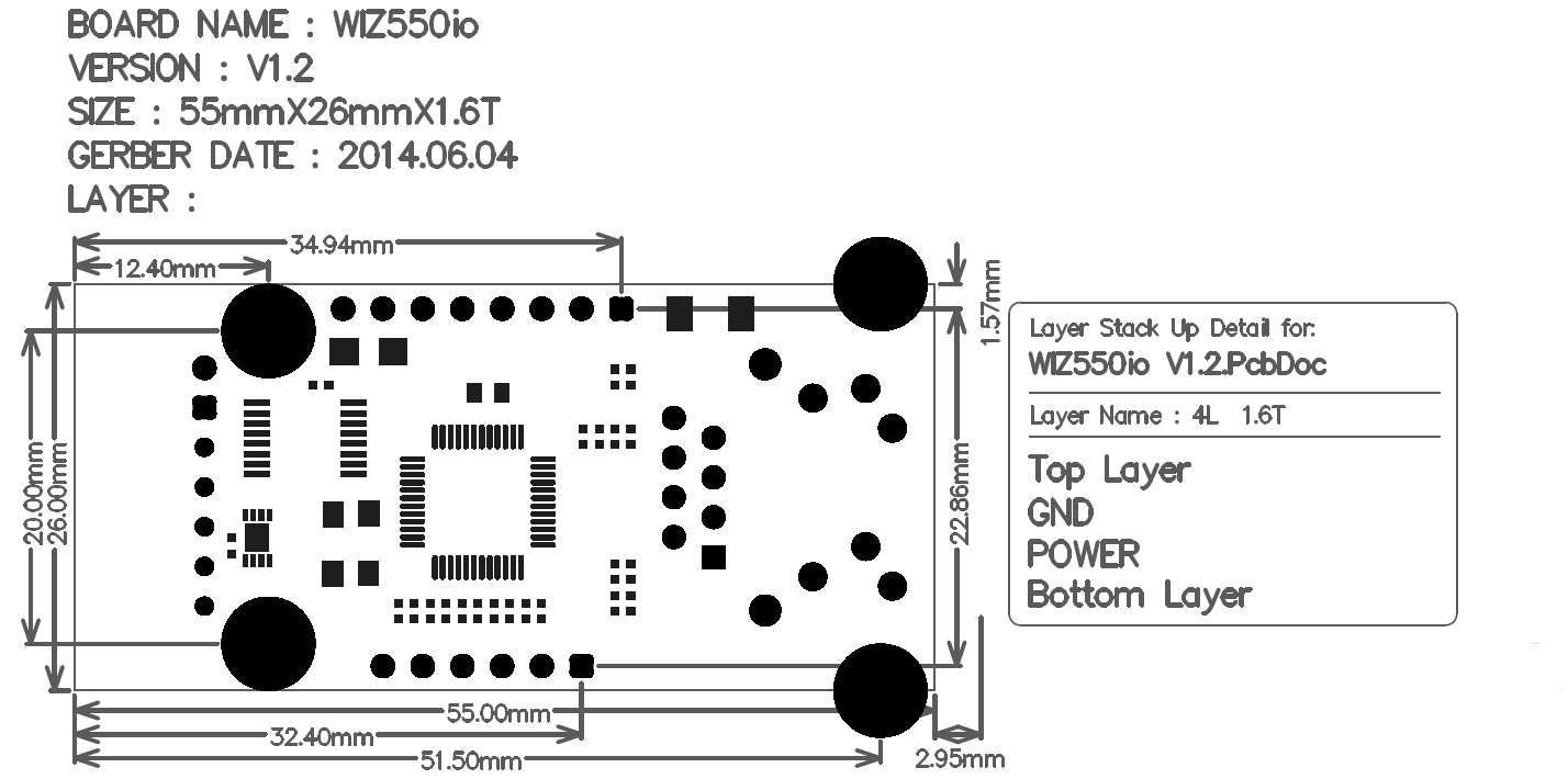
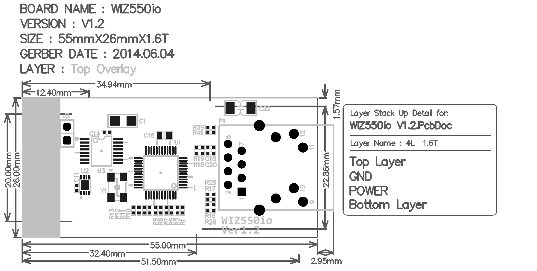
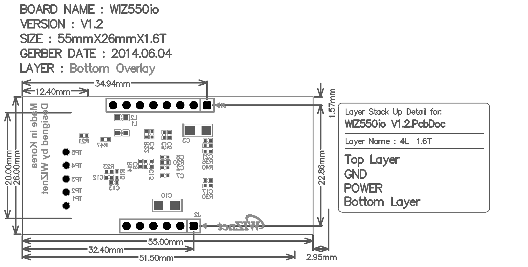
Mechanical Information
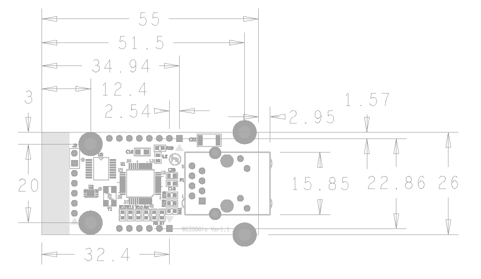
Same to Ver1.1 and Ver1.2 PCB all size and hole size. There is little change in all parts placement.
- PCB Size: 54 mm × 26 mm
- Overall Height: 24 mm (± 0.5 mm)
- Top View:
- Bottom View:
- Drill Map: