W5500-io
W5500-io
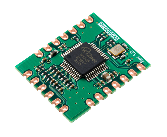
The W5500-io is a compact plug-in network module featuring the W5500 hardwired TCP/IP chip with an integrated PHY. It allows users to add Ethernet functionality to embedded systems without complex hardware design. Fully compatible with W5100S-io and W6100-io modules, W5500-io enables quick evaluation and integration of Ethernet connectivity.
Pin Information
- ALL
- J1
- J2
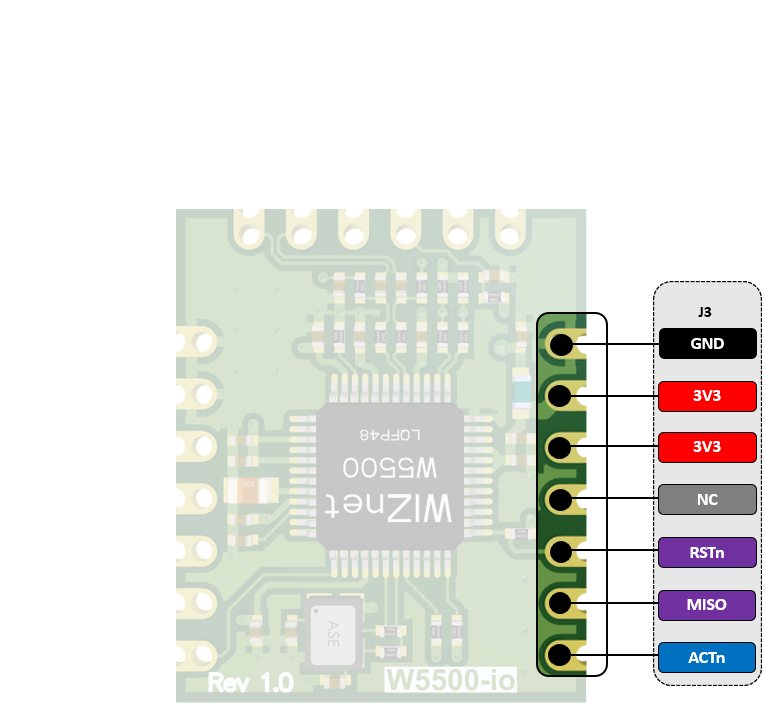
- J3
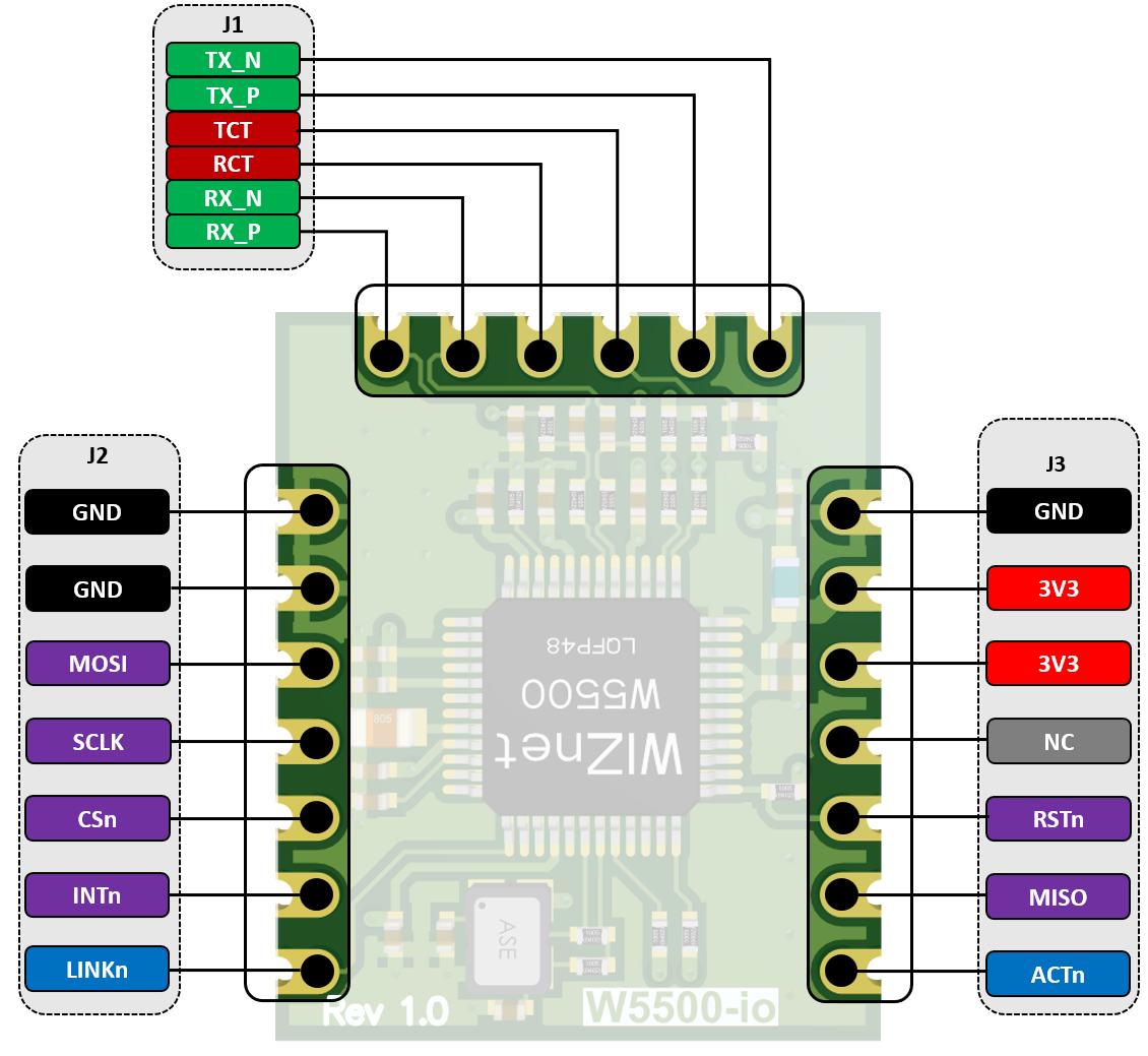
J1 — Ethernet Magnetics Interface
| Pin | Type | Name | Description |
|---|---|---|---|
| 1 | I | RX_P | Differential receive (positive) |
| 2 | I | RX_N | Differential receive (negative) |
| 3 | P | RCT | RX centre tap; connect to transformer centre tap |
| 4 | P | TCT | TX centre tap; connect to transformer centre tap |
| 5 | O | TX_P | Differential transmit (positive) |
| 6 | O | TX_N | Differential transmit (negative) |
J2 — SPI and Status Signals
| Pin | Type | Name | Description |
|---|---|---|---|
| 1 | P | GND | Ground |
| 2 | P | GND | Ground |
| 3 | I | MOSI | SPI Master‑Out/Slave‑In input |
| 4 | I | SCLK | SPI clock input |
| 5 | I | CSn | Chip‑select input (active low) |
| 6 | O | INTn | Interrupt output (active low). Low = interrupt pending, High = no interrupt |
| 7 | O | LINK | Link status output. Low = link OK, High = no link |
J3 — Power and Additional Signals
| Pin | Type | Name | Description |
|---|---|---|---|
| 1 | P | GND | Ground |
| 2 | P | 3.3V | Power supply (3.3 V) |
| 3 | P | 3.3V | Power supply (3.3 V) |
| 4 | – | NC | Not connected |
| 5 | I | RSTn | Module reset (active low). Hold low for ≥ 500 µs to reset |
| 6 | O | MISO | SPI Master‑In/Slave‑Out output |
| 7 | O | ACTn | Activity LED indicator. Low = carrier sense active, High = no carrier sense |
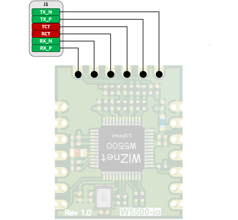
J1 — Ethernet Magnetics Interface
| Pin | Type | Name | Description |
|---|---|---|---|
| 1 | I | RX_P | Differential receive (positive) |
| 2 | I | RX_N | Differential receive (negative) |
| 3 | P | RCT | RX centre tap; connect to transformer centre tap |
| 4 | P | TCT | TX centre tap; connect to transformer centre tap |
| 5 | O | TX_P | Differential transmit (positive) |
| 6 | O | TX_N | Differential transmit (negative) |
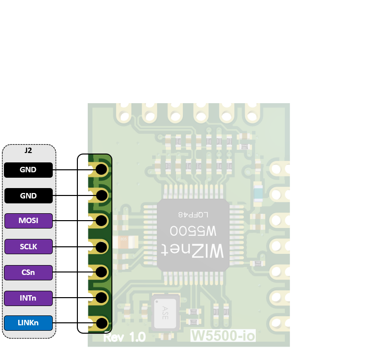
J2 — SPI and Status Signals
| Pin | Type | Name | Description |
|---|---|---|---|
| 1 | P | GND | Ground |
| 2 | P | GND | Ground |
| 3 | I | MOSI | SPI Master‑Out/Slave‑In input |
| 4 | I | SCLK | SPI clock input |
| 5 | I | CSn | Chip‑select input (active low) |
| 6 | O | INTn | Interrupt output (active low). Low = interrupt pending, High = no interrupt |
| 7 | O | LINK | Link status output. Low = link OK, High = no link |
J3 — Power and Additional Signals
| Pin | Type | Name | Description |
|---|---|---|---|
| 1 | P | GND | Ground |
| 2 | P | 3.3V | Power supply (3.3 V) |
| 3 | P | 3.3V | Power supply (3.3 V) |
| 4 | – | NC | Not connected |
| 5 | I | RSTn | Module reset (active low). Hold low for ≥ 500 µs to reset |
| 6 | O | MISO | SPI Master‑In/Slave‑Out output |
| 7 | O | ACTn | Activity LED indicator. Low = carrier sense active, High = no carrier sense |
Features
- Compact plug-in Ethernet module
- Hardware compatible with W5100S-io and W6100-io
- No external design effort for W5500 chip
- High-speed SPI interface
- Power-down and Wake-on-LAN support
- Very small form factor: 20 mm × 24 mm × 2.6 mm
Electrical Characteristics
- DC Characteristic
- Power Dissipation
DC Characteristic
| Symbol | Parameter | Pins | Min | Typ | Max | Unit |
|---|---|---|---|---|---|---|
| VDD | Supply voltage | 3.3 V | 2.97 | 3.3 | 3.63 | V |
| VIL | High-level input | ALL | 2.0 | – | 5.5 | V |
| VIH | Low-level input | ALL | –0.3 | – | 0.8 | V |
| VOL | Low-level output | ALL | – | – | 0.4 | V |
| VOH | High-level output | ALL | 2.4 | – | – | V |
| IDD | Supply current (Normal) | 3.3 V | – | 132 | – | mA |
| IPD | Supply current (Power-down) | 3.3 V | – | 13 | – | mA |
Power Dissipation
| Condition | Typ | Unit |
|---|---|---|
| 100 Mb/s Link | 128 | mA |
| 10 Mb/s Link | 75 | mA |
| Un-Link (Auto-negotiation) | 65 | mA |
| 100 Mb/s Tx | 132 | mA |
| 10 Mb/s Tx | 79 | mA |
| Power-down mode | 13 | mA |
Documentation
This section provides key documentation, including user manuals and datasheets, to help you understand product features, specifications, and usage.
| Title | Description | Link | Notes |
|---|---|---|---|
| Datasheet | Technical specifications and features of the W5500 chip | - |
SPI operation of W5500-io follows one of W5500. For more information about SPI operation of W5500-io, please refer to W5500 Datasheet.
Software Resources
- Driver
- Application Note
Driver
| Resource | Description |
|---|---|
| Official WIZnet driver library for W5500 and other chips |
The ioLibrary_Driver is an MCU-independent library for WIZnet W5x00, W6x00 chips .
It provides implementations of essential TCP/IP services, enabling developers to build network applications with minimal MCU dependencies.
Supported services
DHCP, DNS, MQTT, SNTP, TFTP, HTTP Server
Application Note
| Example Name | Description | Notes |
|---|---|---|
| How to use TCP Function | ITCP Function handles IPv4 layer communication | |
| How to use UDP Function | UDP Function handles IPv4 layer communication | |
| How to use IPRAW Mode | IPRAW Mode handles IPv4 layer communication | |
| How to use PPP/PPPoE | PPP is Link-Layer protocol for point-to-point |
These application notes explain how to use W5500's core networking functions including TCP, UDP, IPRAW mode, and PPPoE protocols.
Hardware Resources
This section provides essential hardware resources, including schematics, 3D models, and part lists for your reference.
| Title | Revision | Description | Download | Notes |
|---|---|---|---|---|
| schematic | 1.0 | Circuit diagram for hardware design reference | ||
| 3D File | 1.0 | 3D model for mechanical design and visualization | ||
| Part list | 1.0 | List of components used in the hardware |
Mechanical Information

- PCB size: 24 mm × 20 mm × 1.0 mm
- Overall height: 2.6 mm (including components)