Getting Started with the W6100-EVB
Check the board
**If you have just purchased W6100-EVB, follow the procedure presented below: **
Connect your board to a PC using USB and connect LAN cable. USB is
Micro B USB type. W6100-EVB doesn't care uses Micro USB B type or
DC-JACK(DC-5V) Don't forget: It
must be supplied DC-5V
The W6100-EVB can use be Micro USB B type or DC-JACK to the power
supply. Users can chooseone of these options.
LAN Connector
When users did connect to LAN cable, users should be check
RJ-45(ethernet connector) LEDs. There are two indicator LEDs in RJ-45.
Orange LED indicates 100M ACT. Green LED indicates LINK.
Hello World
This section is descriptive to W6100-EVB operation. let the following points for the board operation. W6100-EVB supported to eclipse loopback example code. Make new W6100-EVB Project is clicking on this link. If you want to know "How to download the program" click on this link.
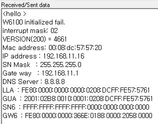
1. Serial Debug message print out
The board outputs serial "debug" message via Micro B USB port (virtual
COM Port). This will give you info about network configuration and
loopback socket.
Check the virtual COM port number in your system's properties.
Please connect with any terminal to that serial port with
115200.8.N.1.
4. Loopback test
If you need detailed figures, please refer
to the below link.
TCP and
UDP loopback
test
The loopback example runs with a TCP session and a UDP session.
First, Board and your PC should have the network config with the same
network range.
If you want to modify board-side, edit the following code in
[src>>LB_main.c] with the same range which your PC has. If you want
to modify your PC-side, refer to IP
configuration.
wiz_NetInfo gWIZNETINFO = { .mac = {0x00,0x08,0xdc,0x57,0x57,0x20},
                            .ip = {192,168,11,16},
                            .sn = {255, 255, 255, 0},
                            .gw = {192, 168, 11, 1},
                            .dns = {8, 8, 8, 8},
                            .dhcp = NETINFO_STATIC,
                            .lla = {0xfe,0x80, 0x00,0x00,
                                 0x00,0x00, 0x00,0x00,
                                 0x02,0x08, 0xdc,0xff,
                                 0xfe,0x57, 0x57,0x61},
                            .gua={0x20,0x01,0x02,0xb8,
                                 0x00,0x10,0x00,0x01,
                                 0x02,0x08,0xdc,0xff,
                                 0xfe,0x57,0x57,0x61},
                            .sn6={0xff,0xff,0xff,0xff,
                                 0xff,0xff,0xff,0xff,
                                 0x00,0x00,0x00, 0x00,
                                 0x00,0x00,0x00,0x00},
                            .gw6={0xfe, 0x80, 0x00,0x00,
                                  0x00,0x00,0x00,0x00,
                                  0x02,0x00, 0x87,0xff,
                                  0xfe,0x08, 0x4c,0x81},
                            };
TCP
- Port 5000 : IPv6
- Port 5001 : IPv4
- Connect to Board
- Using Hercules test program or others, try to connect to board with xxx.xxx.xxx.xxx listen port 5000.
- When connected
- send data to board
- check whether the loopback data is same to what it sent before.
- When failed to connect
- Check link status.
- Check ping test
- Check network config.
- Check the security program as virus vaccines and fire-wall on your PC.
Firmware
W6100-EVB firmware project based on TrueSTUDIO. For more details about TrueSTUDIO, please refer to below link.
Download the Libraries and Application example source code for W6100-EVB
How to upload firmware
Flash programming via UART
1. How to use W6100-EVB ISP mode
Press the 'Boot0' push button switch on board until turn on the board after reset or power supply.
2. Run the STMicroelectronics Flash loader demonstrator
STMicroelectronics Flash loader demonstrator is a program to perform
in-system programming (ISP) of the MCU flash via its UART.
🌎'ST Flash lodaer
demonstrator' download
page
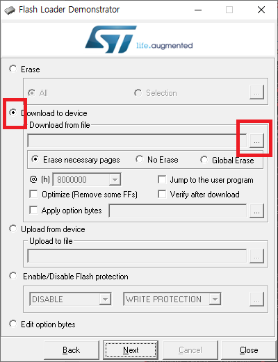
3. Tool settings
Set the settings on main window of Flash loader demonstrator program. It
is easy to set along with each step.
The figure below shows the default configuration for W6100-EVB.
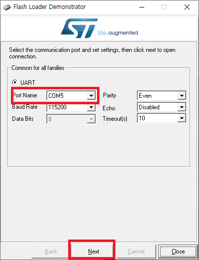
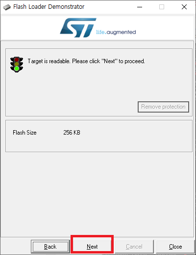
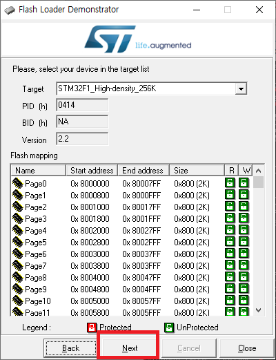
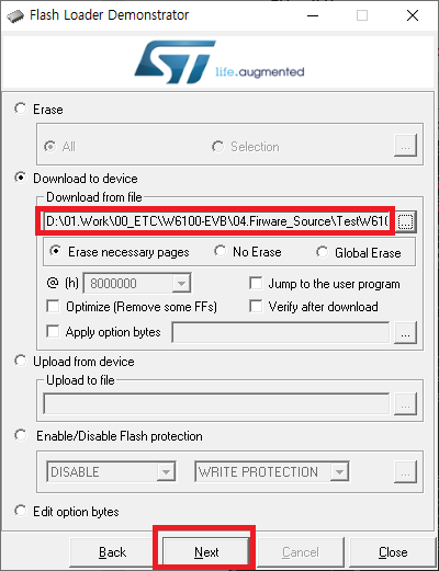
4. Click to 'Next' button
refer to below pictures If you do not go to the next page in flash loader demonstrator, users try again this action. 'Press the 'Boot0' push button switch on board until turn on the board after reset or power supply.'
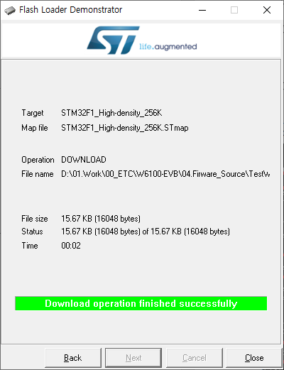
5. Run the new program
After finish to flash programming and board reset, The MCU will be running
the program
When running to loopback program, ie as below picture serial debug
message print out.