Datasheet(Eng)
Overview
This page provides information about the hardware of WIZ550web and its Baseboard as following:
- Basic Hardware Specification
- Operating Characteristics & I/O Characteristics
- Reference Schematics
- Dimension information
The revision history will be updated in this page in case of any changes of hardware specification or exterior design.
Hardware Specification
WIZ550web
- MCU : STM32F103RCT6 (256KB Flash, 48KB SRAM)
- TCP/IP Controller : W5500
- RJ45(Integrated Transformer) : J1B1211CCD
- External Flash Memory : AT45DB081D
- EEPROM : 24AA64T-I/OT
- 2.54mm Pin Header x 2
WIZ550web Pinout
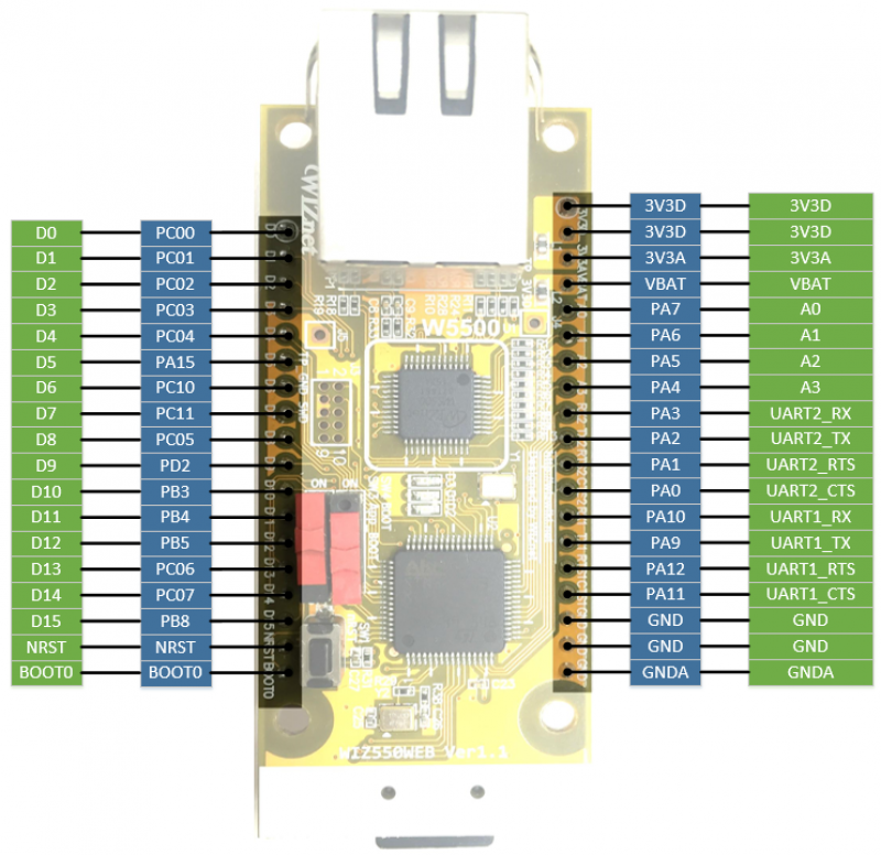
Pin Description
As it is used in the EVB and for the web-server by default
| Ref No. | Pin No. | Symbol | Type | Description |
|---|---|---|---|---|
| J1 | 1 | D0 | I/O | Digital 0 I/O |
| ::: | 2 | D1 | I/O | Digital 1 I/O |
| ::: | 3 | D2 | I/O | Digital 2 I/O |
| ::: | 4 | D3 | I/O | Digital 3 I/O |
| ::: | 5 | D4 | I/O | Digital 4 I/O |
| ::: | 6 | D5 | I/O | Digital 5 I/O |
| ::: | 7 | D6 | I/O | Digital 6 I/O |
| ::: | 8 | D7 | I/O | Digital 7 I/O |
| ::: | 9 | D8 | I/O | Digital 8 I/O / Boot Pin |
| ::: | 10 | D9 | I/O | Digital 9 I/O |
| ::: | 11 | D10 | I/O | Digital 10 I/O |
| ::: | 12 | D11 | I/O | Digital 11 I/O |
| ::: | 13 | D12 | I/O | Digital 12 I/O |
| ::: | 14 | D13 | I/O | Digital 13 I/O |
| ::: | 15 | D14 | I/O | Digital 14 I/O |
| ::: | 16 | D15 | I/O | Digital 15 I/O |
| ::: | 17 | NRST | I | System Reset Input, Active Low |
| ::: | 18 | BOOT0 | I | BOOT0 Input, Active High |
| Ref No. | Pin No. | Symbol | Type | Description |
|---|---|---|---|---|
| J2 | 1 | 3V3D | P | Supply DC +3.3V , Digital Power |
| ::: | 2 | 3V3D | P | Supply DC +3.3V , Digital Power |
| ::: | 3 | 3V3A | P | Supply DC +3.3V , Analog Power |
| ::: | 4 | VBAT | P | Supply DC +3.3V , Low Power Mode |
| ::: | 5 | A0 | I | Analog 0 Input |
| ::: | 6 | A1 | I | Analog 1 Input |
| ::: | 7 | A2 | I | Analog 2 Input |
| ::: | 8 | A3 | I | Analog 3 Input |
| ::: | 9 | UART2_RX | I | Receiver input for UART2 |
| ::: | 10 | UART2_TX | O | Transmitter output for UART2 |
| ::: | 11 | UART2_RTS | O | Request To Send output for UART2 |
| ::: | 12 | UART2_CTS | I | Clear To Send input for UART2 |
| ::: | 13 | UART1_RX | I | Receiver input for UART1 |
| ::: | 14 | UART1_TX | O | Transmitter output for UART1 |
| ::: | 15 | UART1_RTS | O | Request To Send output for UART1 |
| ::: | 16 | UART1_CTS | I | Clear To Send input for UART1 |
| ::: | 17 | GND | P | Digital Power Ground |
| ::: | 18 | GND | P | Digital Power Ground |
| ::: | 19 | GNDA | P | Analog Power Ground |
WIZ550web Baseboard
- DC 9~24V Power Input
- Digital Output 8EA (Relay - HR91C-05)
- Digital Input 8EA (Photocouplers - TLP290-4)
- Analog Input 4EA
- RS-232C
- RS-422
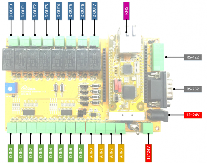
WIZ550web Baseboard Pinout
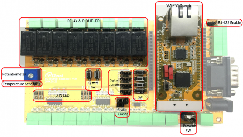
WIZ550web Baseboard Callout
Digital Output Port
WIZ550web Baseboard has eight (D0-D7) relay output stage. Below is a
photo of basic internal circuit. Jumper, relay NC (Normal close) and NO
(Normal Open) can be set. 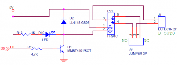 See
the table below for State action.
See
the table below for State action.
| Input value | Relay status value | NC output value | NO output value |
|---|---|---|---|
| 0 | OFF | Close | Open |
| 1 | ON | Open | Close |
Output port voltage and current characteristics, see the table below.
| NO | 5A 28VDC | 10A 125VAC | 5A 250VAC |
|---|---|---|---|
| NC | 3A 28VAC | 5A 125VDC | 3A 250VDC |
Digital Input Port
WIZ550web Baseboard has eight (D8 to D15) Photocoupler via a digital input columns. Below is a photo of basic internal circuit. There is no polarity input, and ON/OFF is distinguished from this potential difference between the two input signals.
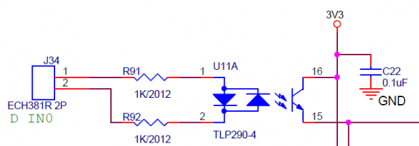
See the table below for the electrical characteristics of the input.
| Under 1.4V | Low |
|---|---|
| Over 2.1V | High |
| Max Voltage | 24V |
| Potential difference | No. There are two input signals On/Off by potential difference |
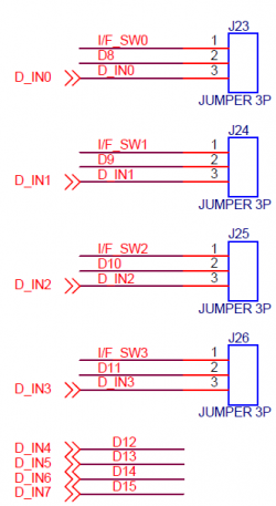
Four (D8-D11) digital inputs are connected as shown in tact switch
inside the Baseboard, and these connections have select Jumper J23-J26.
Analog Input Port
WIZ550web Baseboard has four (A0-A3) analog input columns. Below is a
photo of basic internal circuit. It is possible to simply enter 0 to 12V
and has entered in the WIZ550WEB through the internal circuitry.
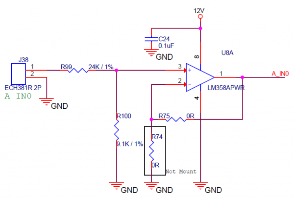
Two of the Analog Input (A0, A1) have connected with a variable resistor
(10K) and a temperature sensors (TC1047AVNB) in the Baseboard, this
connection can opt to J26, J28 Jumper. 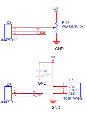
AC/DC Characteristics
WIZ550WEB
General Operating Conditions
| Symbol | Parameter | Pins | Min | Typ | Max | Unit |
|---|---|---|---|---|---|---|
| VDD | Standard operating voltage | 3V3D | 2 | 3.3 | 3.6 | V |
| VDDA | Analog operation voltage (ADC not used) | 3V3A | 2.0 | 3.3 | 3.6 | V |
| ::: | Analog operation voltage (ADC used) | 3V3A | 2.4 | 3.3 | 3.6 | V |
| VBAT | Backup operating voltage | VBAT | 0.8 | 3.3 | 3.6 | V |
| VIN | I/O Digital input voltage | D0~D15 | 0 | - | VDD+0.3 | V |
| ::: | I/O Analog input voltage | A0~A3 | 0 | - | VDD+0.3 | V |
| ::: | BOOT0 | BOOT0 | 0 | - | 5.5 | V |
| ::: | NRST | NRST | 0 | - | VDD+0.3 | V |
I/O Static Characteristic
| Symbol | Parameter | Pins | Min | Typ | Max | Unit |
|---|---|---|---|---|---|---|
| VIL | Low level input voltage | D0~D15 | -0.5 | - | 0.7 | V |
| VIH | High level input voltage | D0~D15 | 2.0 | - | VDD | V |
| VIO | Output current sunk by any I/O and control pin | D0~D15 | - | - | 25 | mA |
| ::: | Output current source by any I/O and control pin | D0~D15 | - | - | -25 | mA |
| VIL(NRST) | NRST Input low level voltage | NRST | -0.5 | - | 0.8 | V |
| VIH(NRST) | NRST Input high level voltage | NRST | 2 | - | 3.3 | V |
Reference Schematic & Parts
Schematic
| 항목 | Version | Schematic |
|---|---|---|
| WIZ550web | 1.1 | Download |
| WIZ550web Baseboard | 1.0 | Download |
Parts Datasheet
| Parts | Descripsion | Datasheet |
|---|---|---|
| STM32F103RCT6 | ARM 32-bit Cortex™-M3 CPU Core | STM32F103RCT6 |
| W5500 | WIZnet TCP/IP Chip | W5500 |
| AT45DB081D-SU | 8-Megabit Serial Flash Memory | AT45DB081D-SU |
| 24AA64T-I/OT | 64K I2C™ Serial EEPROM | 24AA64T-I/OT |
| J1B1211CCD | Transformer + RJ45 + LED, Industrial | J1B1211CCD |
| HR91C-05 | 1 pole, 3-10A Relay, 1c(SPDT) | HR91C-05 |
| SP3485EN | Low Power Half-Duplex RS-485 Transceivers | SP3485EN |
| SP3232EBEY | True +3.0V to +5.5V RS-232 Transceivers | SP3232EBEY |
| TC1047AVNB | Temperature to Voltage Sensor | TC1047AVNB |
| LM358APWR | Dual Operational Amplifiers | LM358APWR |
| TLP290-4 | 4-Channel Transistor-Output Photocouplers | TLP290-4 |
| AOZ1210AI | EZBuck 2A Simple Buck Regulator | AOZ1210AI |
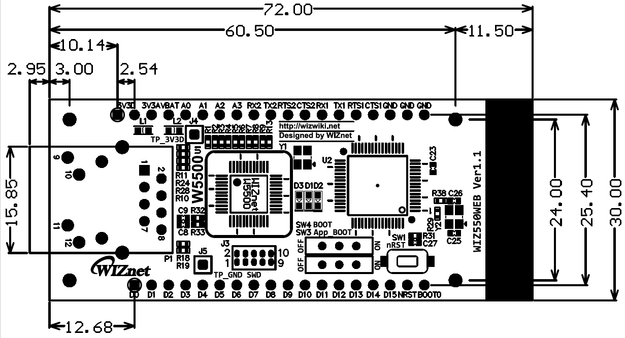
WIZ550web
74.95mm(W) x 30mm(L) x 24mm(H) (±0.5)
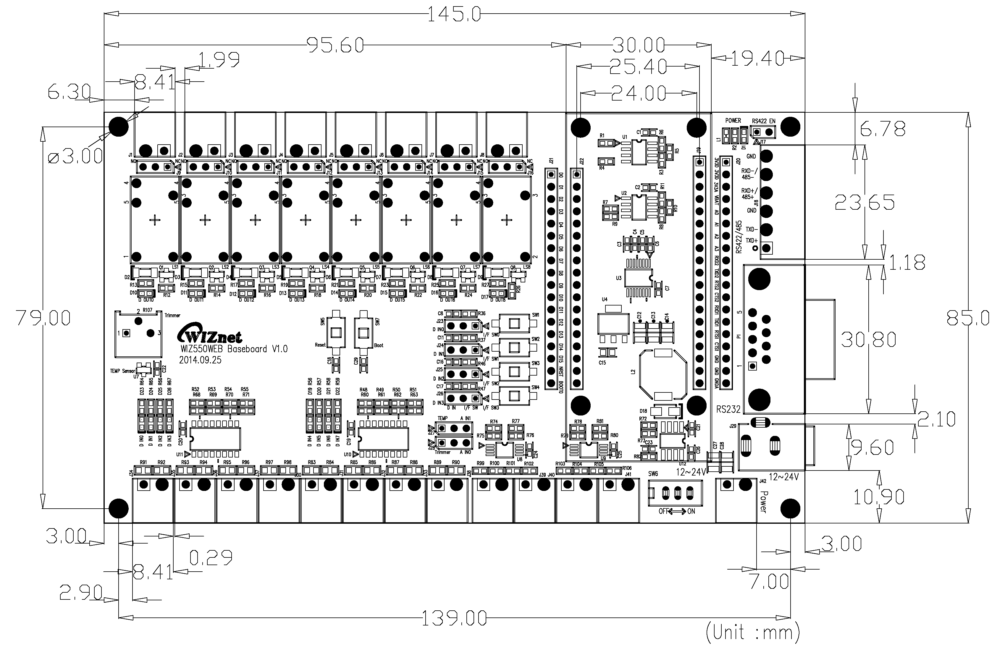
WIZ550web Baseboard
145mm(W) x 85mm(L) x 28mm(H) (±0.5)