User's Manual (Programmer's Guide)-[EN]
Overview
This page provides detailed information about AT commands set and how to use the Configuration tool, which retrieves and sets all configurations of WIZ550SR via Ethernet. Users can change any value of the WIZ550SR and communicate with the peer system through TCP(or UDP) socket by sending AT commands.
WIZ550SR AT Command Set
This section provides a list of WIZ550SR AT commands and their functions. Users can input commands and parameters through USART line.
Enter/Exit Command Mode
The command mode is entered by sending the "Trigger Code" (default 2B 2B
2B in Hex) to the serial port of the WIZ550SR module.
This three byte Trigger Code need to be send without any character
before and after the three byte = also without CR or LF for 500ms
time.
The command mode is closed by sending "AT+MDATA/r/n"
The Trigger Code can be en/disabled and also changed with the config
tool.
The three byte Trigger Code need to be
isolated = without CR(0x0D), LF(0x0A)
Every command starts with “AT”. Any other initial character will cause
an error in return. Commands and parameters are all ASCII characters,
i.e. when you input 'AT+NSTAT', you should input ASCII characters 'A',
'T', '+', 'N', 'S', 'T', 'A', 'T' and 'Enter Key' which is CR, LF (0x0d,
0x0A).
All commands should be terminated with
CR(0x0D), LF(0x0A)
Some parameters are mandatory and others are optional. Parameters must be entered in the order of format column given by the command tables. Although the optional parameter is not used, the comma delimiters ',' must still be included in the command. In most cases, valid commands return the character [S] and invalid inputs return [F]. The possible responses sent from WIZ550SR to the user are described as Responses. Below are examples of user input. As you can see, WIZ550SR return “\r\n” back instead of “\r”, which means user (host system) always handle '\r\n' as the only delimiter.
| Input by User | AT\r\n (0x61 0x74 0x0d 0x0a) |
|---|---|
| Output from WIZ550SR | [S]\r\n (0x5b 0x53 0x5d 0x0d 0x0a) |
Responses
Response Format
[(Type),(Id),(Param1),(Param2),(Param3),(Param4),(Param5),(Param6)]↓(Data)↓
-
(Type): Type of response. It can be one of S, D, F, W, R and V.
-
(Id): Socket Identifier. This is the mandatory in Async mode.
-
(Param1) ~ (Param6): ): These are included in case of commands retrieving module's setting value.
-
↓: This means 'Enter' key as delimiter and CR, LF(0x0d, 0x0a) are its real value.
-
(Data): When huge data are needed, 'Data' will be followed in case of Type of response, D and R.
Responses are listed below.
| Response | Description |
|---|---|
| Success Response | [S,(Id),(Param1),(Param2),(Param3),(Param4),(Param5),(Param6)]↓ Command Request Success, outputs with param when it's needed. |
| Success Dump Response | [D,(Id),(Size)]↓(Data)↓ Command Request Success, Outputs large data include 'Enter key' value. |
| Fail Response | [F,(Id),(ErrorCode),(ErrorParam)]↓ Command Request Fail, outputs with param when it's needed. |
| Wait Response | [W,(Id)]↓ Command is started with ID in Async mode. |
| Data Receive Response | [R,(SockId),(ReceivedSize),(SrcIP),(SrcPort)]↓(Data)↓ Outputs the received data. |
| Event Response | [V,(Id),(EventCode)]↓ Event occurred. |
-
(Id): 0 - System ID or 0~n - Socket Number
-
(Size): Byte size of the output data
-
(ErrorCode): Error Code
-
(ErrorParam): Value of description for Error Code
-
(SockId): Socket Identifier of the socket which received data
-
(ReceivedSize): Byte size of received data
-
(SrcIP): Sender's IP address. This is mandatory in case of UDP & TCP Client. In case of TCP Server this is omitted.
-
(SrcPort): Sender socket's port number. This is mandatory in case of UDP & TCP Client.In case of TCP Server this is omitted.
-
(EventCode): Indication of which event happened.
Error Code
General Error Code
| Code | Error Name | Description |
|---|---|---|
| 0 | ERR_Undefined | Undefined Error |
| 1 | ERR_WrongOperator | Wrong Operator |
| 2 | ERR_WrongCommandSign | Wrong Command Sign |
| 3 | ERR_WrongArguments | Wrong Arguments |
| 4 | ERR_OurofRange | Parameter is out of Range |
| 5 | ERR_FuncDisabled | This function is disabled |
| 6 | ERR_NotAllowed | Not Allowed |
| 7 | ERR_CommandBusy | Command Busy |
| 8 | ERR_CommandTimeout | Command Timeout |
Socket Error Code
| Code | Error Name | Description |
|---|---|---|
| 10 | ERR_SockNotAvail | Socket Not Available |
| 11 | ERR_SockClosed | Socket Closed |
| 12 | ERR_SockPortNumNotAvail | Port Not Available |
| 13 | ERR_SockNotConnected | Not Connected |
| 14 | ERR_SockWrongAddr | Wrong Address |
| 15 | ERR_SockDataNotAvailable | Data Not Available |
Other Error Code
| Code | Error Name | Description |
|---|---|---|
| 20 | ERR_NoFreeMem | No Free Memory |
Event Code
Socket Event Code
| Code | Socket Event Name | Description |
|---|---|---|
| 0 | EVENT_SockConnected | Connected. Socket transition from Listen state to established state |
| 1 | EVENT_SockDisconnected | Disconnected. Socket transition from established state to disconnected state |
| 2 | EVENT_SockClosed | Closed. Socket transition to closed state |
| 3 | EVENT_SockDataRcvd | Data Received. The corresponding socket received data from its peer |
Network Commands
| Command | Prop. | Input Parameter | Response |
|---|---|---|---|
| AT+NSET | None or ? | [S,,S,(IP),(SN),(GW),(DNS)] | |
| ::: | ::: | ::: | [S,,D] |
| ::: | = | S,(IP),(SN),(GW),(DNS) | [S] |
| ::: | ::: | D | [S] |
| ::: | - | num,Param | [S] |
| AT+NSTAT | None or ? | [S,,S/D,(IP),(SN),(GW),(DNS)] | |
| AT+NMAC | None or ? | [S,,(MAC)] | |
| ::: | = | (MAC) | [S] |
| AT+NOPEN | = | S/C/U,(SrcPort),(DstIP),(DstPort) | [W,(SockId)] [S,(SockId)] |
| ::: | ::: | A | ::: |
| AT+NCLOSE | = | (SockId) | [W,(SockId)] [S,(SockId)] |
| AT+NSEND | = | (SockId),(size),(DstIP),(DstPort) | [W,(SockId)] [S,(SockId)] |
| AT+NSOCK | None or ? | [D,,(Size)]↓(Data) | |
| ::: | = | (SockId) | [S,,S/C/U,(SrcPort),(DstIP),(DstPort)] |
AT+NSET
Format:
AT+NSET=<DHCP>,<IP>,<SN>,<GW>,<DNS>
- Meaning: Network Configuration
< DHCP>: Static/DHCP
| Parameter | Meaning |
|---|---|
| S | DHCP Off, Static |
| D | DHCP On, DHCP Client |
< IP>: IP Address (Optional)
< SN>: Subnet Mask (Optional)
< GW>: Gateway Address (Optional)
< DNS>: DNS Address(Optional)
- Response:
[S]
- Example 1:
AT+NSET\r\n AT+NSET?\r\n
- Meaning: Get Current Network Setting
Note that < IP>, < SN>, < GW>, < DNS> address of response are not actual addresses, but addresses stored in the memory. So when DHCP is on, they are usually different from actual addresses.
- Response:
[S,,S,192.168.11.100,255.255.255.0,192.168.11.1,8.8.8.8]
[S,,D]
- Example 2:
AT+NSET-2,192.168.11.110\r\n
-
Meaning: Update Second Parameter
-
Response:
[S]
AT+NSTAT
Format:
AT+NSTAT
AT+NSTAT?
-
Meaning: Display Current Network Status
-
Response:
[S,,<DHCP>,<IP>,<SN>,<GW>,<DNS>]
- Example 1:
AT+NSTAT\r\n AT+NSTAT?\r\n
-
Meaning: Display Current Network Status
-
Response:
[S,,S,192.168.11.100,255.255.255.0,192.168.11.1,8.8.8.8]
[S,,D]
AT+NMAC
Format:
AT+NMAC
AT+NMAC?
-
Meaning: Get MAC Address
-
Response:
[S,,<MAC>]
- Example 1:
AT+NMAC=00:08:dc:1d:bb:8b\r\n
-
Meaning: Set MAC Address
-
Response:
[S]
- Example 2:
AT+NMAC\r\n
AT+NMAC?\r\n
-
Meaning: Get MAC Address
-
Response:
[S,,00:08:dc:1d:bb:8a]
AT+NOPEN
Format:
AT+NOPEN=<SockType>,<SrcPort>,<DstIP>,<DstPort>
- Meaning: Initialize Socket
< SockType>: Socket Type
| Parameter | Meaning |
|---|---|
| S | TCP Server Socket |
| C | TCP Client Socket |
| U | UDP Socket |
< SrcPort>: Local Port Number
< DstIP>: Destination IP Address
< DstPort>: Destination Port Number
-
Response:
[W,(SockId)]
[S,(SockId)]
-
Example 1:
AT+NOPEN=C,3000,192.168.11.100,3000\r\n
-
Meaning: Create TCP Client Socket
-
Response:
[W,0] [S,0]
[W,0] [F,,1]
- Example 2:
AT+NOPEN=S,5000,,\r\n
-
Meaning: Create TCP Server Socket
-
Response:
[S,,0]
AT+NCLOSE
Format:
AT+NCLOSE=(SockId)
- Meaning: Close Socket
< SockId>: Socket ID
-
Response:
[W,(SockId)]
[S,(SockId)]
-
Example 1:
AT+NCLOSE\r\n
-
Meaning: // Close Socket//
-
Response:
[W,0] [S,0]
[F,,11]
AT+NSEND
Format:
AT+NSEND=<SockId>,<size>,<DstIP>,<DstPort>
- Meaning: Send Data
< SockId>: Socket ID
| Parameter | Meaning |
|---|---|
| S | TCP Server Socket |
| C | TCP Client Socket |
| U | UDP Socket |
< SrcPort>: Local Port Number
< DstIP>: Destination IP Address
< DstPort>: Destination Port Number
-
Response:
[W,(SockId)]
[S,(SockId)]
-
Example 1:
AT+NSEND=0,4\r\n aaaa
-
Meaning: In TCP Server mode, Destination IP and port are not need.
-
Response:
[W,0] [S,0]
Management Commands
| Command | Prop. | Input Parameter | Response |
|---|---|---|---|
| AT | None | [S] | |
| ::: | ? | ::: | [D,,(Size)]↓(Data) |
| AT+MSTAT | None or ? | [S,,(Version)] | |
| AT+MUSART | None or ? | [S,,(BR),(W),(P),(S),(F)] | |
| ::: | = | (BR),(W),(P),(S),(F) | [S] |
| ::: | - | num,Param | [S] |
| AT+MSAVE | None | [S] | |
| AT+MRST | None | [S] | |
| ::: | = | F | [S] |
| AT+MDATA | None | [S] |
AT
Format:
AT
-
Meaning: Terminal Check
-
Response:
[S]
AT+MSTAT
Format:
AT+MSTAT
AT+MSTAT?
-
Meaning: Get Current Version
-
Response:
[S,,<Version>]
AT+MUSART
Format:
AT+MUSART=<BR>,<W>,<P>,<S>,<F>
- Meaning: Serial Interface Configuration
< BR>: Baud rate
| Parameter | Meaning |
|---|---|
| 600 | 600bps |
| 1200 | 1200bps |
| 2400 | 2400bps |
| 4800 | 4800bps |
| 9600 | 9600bps |
| 19200 | 19200bps |
| 38400 | 38400bps |
| 57600 | 57600bps |
| 115200 | 115200bps |
| 230400 | 230400bps |
< W>: Word length
| Parameter | Meaning |
|---|---|
| 7 | 7 bits |
| 8 | 8 bits |
< P>: Parity bit
| Parameter | Meaning |
|---|---|
| N | NONE |
| O | ODD |
| E | EVEN |
< S>: Stop bit
| Parameter | Meaning |
|---|---|
| 1 | 1 bits |
| 2 | 2 bits |
< F>: Flow Control
| Parameter | Meaning |
|---|---|
| 0 | NONE |
| 1 | RTS/CTS |
| 2 | RS422 |
| 3 | RS485 |
- Response:
[S,,<BR>,( <W>, <P>, <S> ) <F>]
-
Example1:
AT+MUSART
AT+MUSART?
-
Meaning: Get Serial Interface Information
-
Response:
[S,,<BR>,( <W>, <P>, <S> ) <F>]
- Example2:
AT+MUSART=,,E,,0
-
Meaning: Set Serial Interface Information
-
Response:
[S]
AT+MDATA
Format:
AT+MDATA
-
Meaning: Terminal Check - exit AT Command mode
-
Response:
[S]
Function Commands
| Command | Prop. | Input Parameter | Input Resp. | Query Response |
|---|---|---|---|---|
| AT+FDNS | None | [D,,(Size)]↓(Data) |
AT+FDNS
Format:
AT+FDNS
-
Meaning: Do DNS Query and then return its result. Using Domain and DNS Server IP what has set via Configuration Tool.
-
Response:
[D,,13] DNS Timeout
[D,,17] 173.194.126.180
Configuration Tool
Description
WIZ550SR Configuration tool is an application program which is based on java and can be used in most OS platforms including Windows, MAC OS and Linux. Please download .jar file and execute it over Java Virtual Machine.
There are two options on how to run the configuration tool.
- Run the jar file from the GUI environment.
- The jar file cannot be opened if the jar file is perceived as a compressed file. In this case, modify the setting of the compression software and do not open the jar file in compressed file method.
- In case of Linux or Mac, the following must be given permission.
- chmod 0755 WIZ550SR_Configuration_Tool.jar
- Enter the following command in the terminal to run the program.
- java -jar WIZ550SR_Configuration_Tool.jar
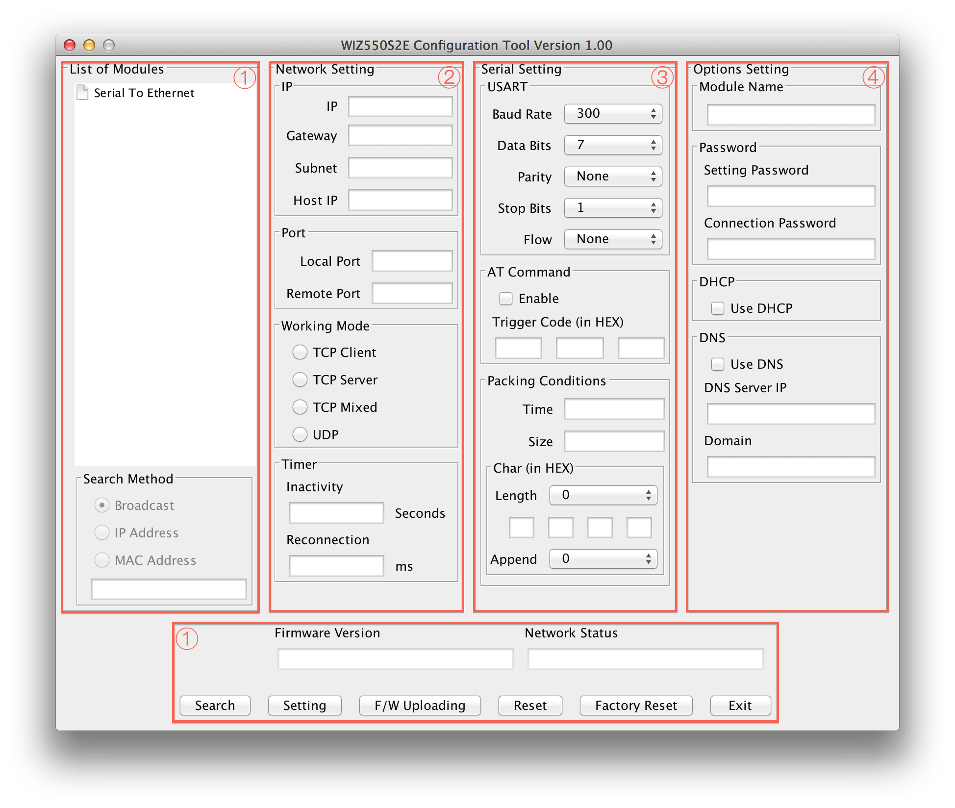
WIZ550SR Configuration tool consists four sections
- Common Configuration Section
- Network Configuration Section
- Serial Configuration Section
- Option Configuration Section
Common Configurations
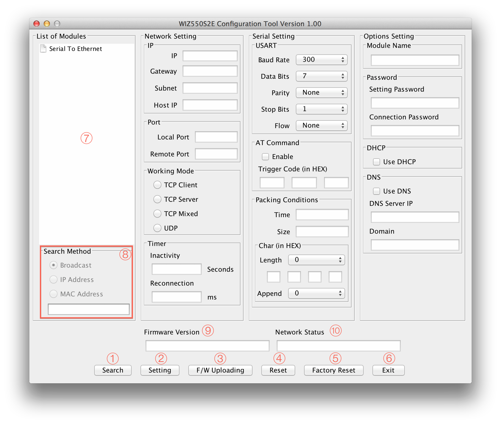
Search
The Search function is used to search for all existing WIZnet's WIZ550 series modules on the same LAN. By using UDP broadcast, it finds all modules on the same subnet, and found devices will be listed in the “Serial to Ethernet” tree(Search Window) with its MAC address.
Setting
This function is used to apply your configurations.
When you select the MAC address from the “Search Window”, the default
value of the module will be displayed. Modify your configurations and
click “Setting” button to apply your settings. The module will
re-initialize and save the changed configurations.
Users can change the configurations by the following steps.
- Select the MAC address of the device which you would like to modify in the “Search Window”
- Modify the settings according to your needs
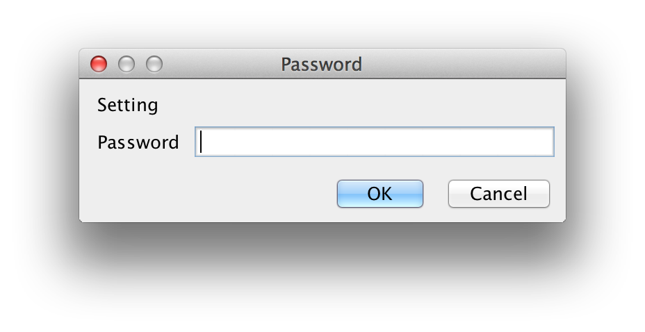
- Click the “Setting” button and then "Password Input Windows" pop up
- Default Password is "WIZnet"
- Input "Setting Password" and Click "OK" button
- The module will be initialized by a re-booting process
- To verify your settings, please click ‘Search’ button and view your new settings
F/W Uploading
Firmware will be uploaded through TFTP. Click “F/W Uploading” Button and
a popup window will shows as follow.
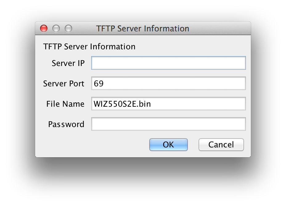
Server IP : TFTP Server IP
Server Port : TFTP Server Port (TFTP default Port : 69) File Name : Firmware File Name Password : Setting Password
☞ WIZ550SR Configure tool is not supported TFTP server. So you use TFTP program separately.
Reset
This is the function which makes Module reboot. This requires password to reboot.
Factory Reset
All setting value is initialized to factory default, if the “Factory Reset” button is clicked. Factory default values of WIZ550SR are listed below.
| Category | Item | Value |
|---|---|---|
| Network | Local IP | 192.168.11.100 |
| ::: | Local Gateway | 192.168.11.1 |
| ::: | Local Subnet | 255.255.255.0 |
| ::: | Local Port | 5000 |
| ::: | Remote Port | 5000 |
| ::: | Working Mode | TCP Server |
| ::: | Inactivity | 0 |
| ::: | Reconnection | 1000 |
| Serial | Baud Rate | 115200 |
| ::: | Data Bits | 8 |
| ::: | Parity | NONE |
| ::: | Stop Bits | 1 |
| ::: | Flow | NONE |
| ::: | AT Command USE | Enable |
| ::: | Trigger Code | 2B/ 2B / 2B |
| ::: | Packing Condition Time | 0 |
| ::: | Packing Condition Size | 0 |
| ::: | Delimeter Length | 0 |
| ::: | Delimeter | 2D / 2D / 2D / 2D |
| ::: | Delimeter Appendix | 0 |
| Options | Module Name | WIZ550SR |
| ::: | Setting Password | WIZnet |
| ::: | Connection Password | WIZnet |
| ::: | DHCP USE | Disable |
| ::: | DNS USE | Disable |
| ::: | DNS Server IP | 8.8.8.8 |
Exit
Close the configuration tool program window.
Search Window
If you click the “Search” button, all MAC addresses on the same subnet will be displayed.
Search Method
Reserved
Firmware Version
It displays the firmware version.
Network Status
This field shows the current status of network connection.
Connected : This means that TCP connection is established. Disconnected : This measn that TCP connection is disconnected. UDP : This means that UDP mode is used.
Network Configurations
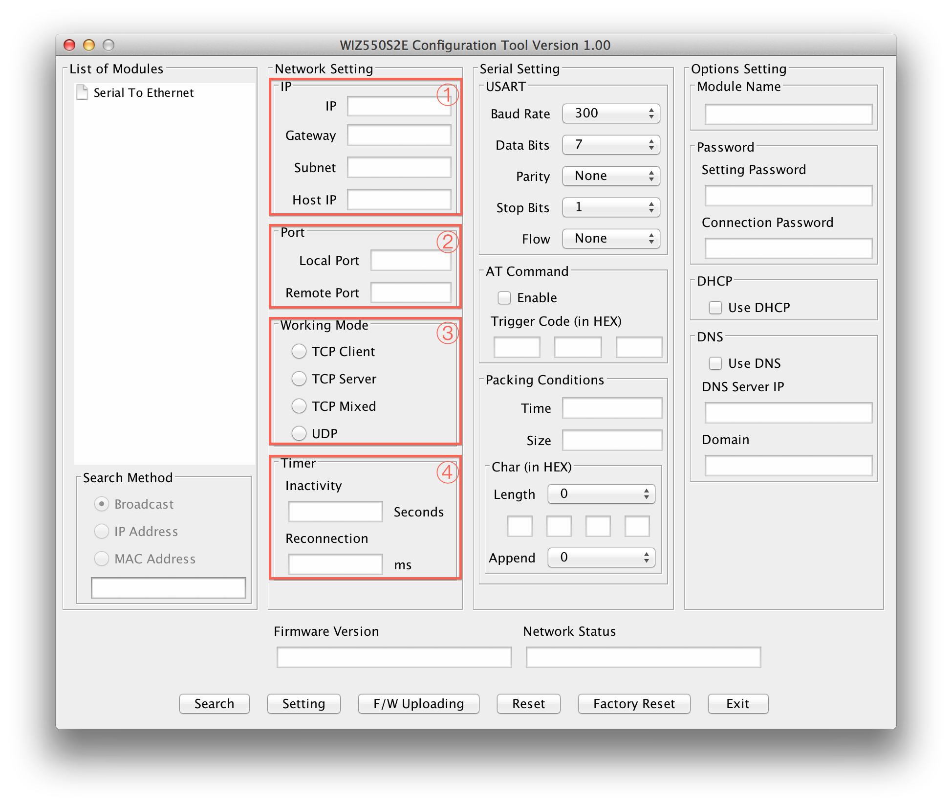
IP
This section is for setting WIZ550SR mode's network information
IP: WIZ550SR's IP Address Gateway: WIZ550SR's Gateway Address Subnet mask: WIZ550SR's Subnet Mask Host IP: Peer system's IP address which WIZ550SR connects(or sends) to, when its operating mode is "TCP Client","TCP Mixed" or "UDP".
☞ If you are unclear about your Local IP, Subnet Mask, Gateway information, you have to get this information from your network administrator. If the IP address is not correct, IP collision or network problems may occur.
Port
This section is for setting WIZ550SR's Port information.
Local port : WIZ550SR's local port number Remote port : Peer system socket's port number which WIZ550SR connects(or sends) to, when its operating mode is "TCP Client","TCP Mixed" or "UDP".
Working Mode
The working mode of WIZ550SR can be divided into TCP Server, TCP Client and TCP Mixed according to the connection establishing method, but UDP processes the data communication without connection establishment.
During TCP server mode, WIZ550SR operates as the server and waits for the connection trial from the client. WIZ550SR operates as the client in TCP Client mode and tries to connect to the server’s IP and Port. Mixed mode supports both Server and Client. The communication process of each mode is as below.
TCP server mode communication
During the TCP Server mode, WIZ550SR waits for the connection request. TCP Server mode can be useful when the monitoring center attempts to connect to the device, while WIZ550SR is installed, in order to check the status or provide commands. Normally WIZ550SR is on the waiting status, and if connection request (SYN) from the monitoring center is received, the connection is established (ESTABLISH), and data communication is processed (Data Transaction), and finally connection is closed (FIN). In order to operate this mode, “Device IP”, “Subnet mask”, “Gateway” and “Local port” should be configured first.
For TCP server mode communication, all network configurations including Local IP, Subnet, Gateway and Local port number should be set correctly.
The Data transmission proceeds as below.
- The host connects to the WIZ550SR which is configured as TCP Server mode.
- As the connection is established, data can be transmitted in both directions
(host -> WIZ550SR / WIZ550SR -> host)
TCP client mode communication
If WIZ550SR is set as TCP Client, it tries to establish connection to the TCP server. To operate this mode, “Device IP”, “Subnet mask”, “Gateway”, “Remote host”, and “Remote port” should be set. If “Remote host” has a domain name, you should use the “DNS server” field. In TCP Client mode, WIZ550SR can actively establish a TCP connection to a host computer when power is supplied.
The Data transmission proceeds as below:
- As power is supplied, WIZ550SR board operating as TCP client mode actively establishes a connection to the TCP server.
- If the connection is complete, data can be transmitted in both directions
(host -> WIZ550SR / WIZ550SR -> host)
TCP Mixed mode Communication
In this mode, WIZ550SR normally operates as TCP Server and waits for the connection request from the peer. However, if WIZ550SR receives data from the serial device before connection is established, it changes to the TCP client mode and sends the data to the TCP server IP. Therefore, during TCP mixed mode, the TCP server mode is operated prior to the TCP client mode.
Like TCP Server mode, the TCP Mixed mode is useful in case where the monitoring center attempts to connect to the serial device, while WIZ550SR is used, to check the device status. In addition to this, if any emergency occurs in the serial device, the module will change to TCP Client mode to establish the connection to the TCP server and deliver the emergency status of the device.
UDP mode Communication
UDP is not a connection oriented protocol but the communication port should be defined well. If UDP mode is selected, the data from serial interface can be defined where to deliver via the “Remote host” and “Remote port.” The WIZ550SR can also be defined where to receive Ethernet data from via the “Remote host” and “Local port” definition.
If the data destination and source are the same, the two IP addresses will also be the same. Please note that the destination and source are using the same port.
Timer
Inactivity
When there is no data transmission, the connection will close automatically after the specified inactivity time. If the default value ‘0’ is set as the Inactivity time, the network connection is maintained even though there is no data transmission. In this case, you should use the ‘Close’ command to close the connection.
This function is useful when there are two or more systems connected to the WIZ550SR module. If one system is connected to the WIZ550SR, other systems cannot connect to the module simultaneously. Therefore, the inactivity time should be set and the other system can connect to the module after the inactivity time is elapsed.
Inactivity Time can also be used if the TCP server system unexpectedly shuts down. In this case, there is no data communication, and WIZ550SR will close the connection and enter into waiting state if the defined inactivity time elapses.
Reconnection
This is the interval time which WIZ550SR tries to connect again after connection is closed. This is valid only in "TCP Client" or "TCP Mixed" having data from serial prior to TCP connection is established.
Serial Configurations
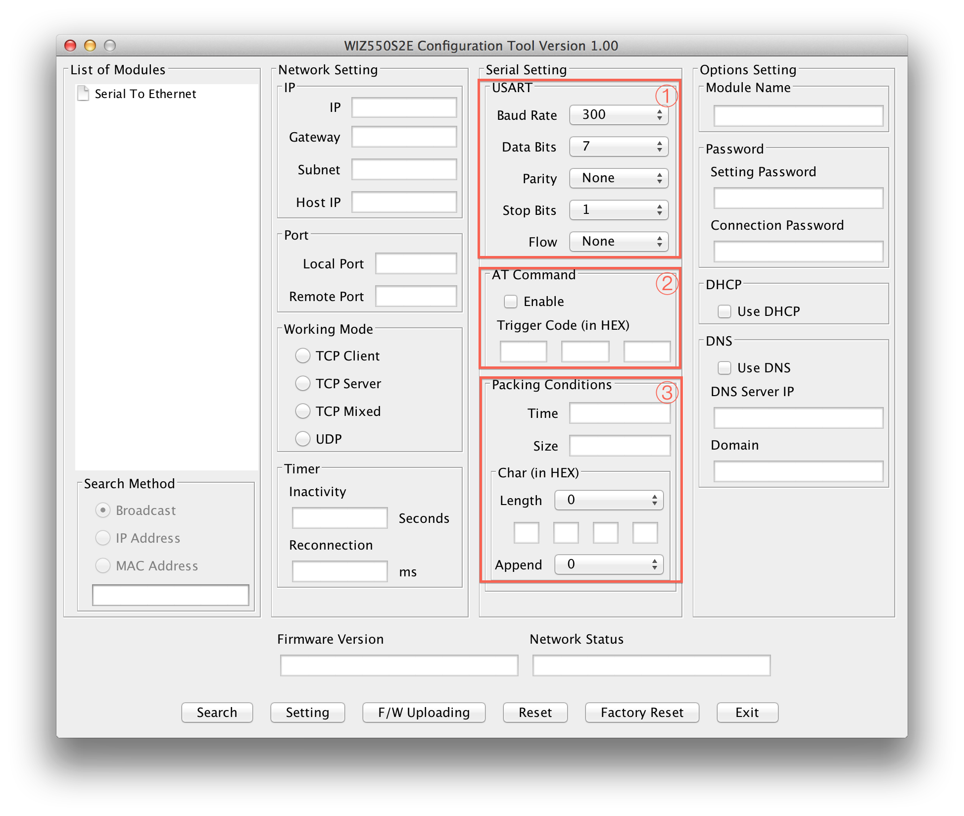
USART
This menu is used for setting the serial port.
Baud Rate : WIZ550SR's Baud Rate Data Bits : WIZ550SR's Data Bits (7,8,9) Parity : WIZ550SR's Parity Bits Stop Bits : WIZ550SR's stop Bits Flow : WIZ550SR's Flow Control & RS422/RS485
AT Command
This function is controlling the module to allow the module could be capable to control the module through serial terminal (AT command).
Module Default setting: Enable
Default trigger to AT command: 2B 2B 2B in Hex.
Packing Conditions
Normally, data received from UART are sent to Ethernet immediately. But in many cases, users want to send data as a chunk of the whole frame without separated ones. This option is for packetizing data into one frame.
Time (0 ~ 65535 ms, ‘0’: Function Disable) :
This field is for specifying time value (in ms) to judge whether one frame is received totally. If the time specified in this field is expired after receiving one byte, then WIZ550SR notice one data frame is finished, make an Ethernet packet with all data in its serial buffer and send it to the peer system via Ethernet. If WIZ550SR receives another byte from UART before the specified time is expired, it restart timer and add the received one to the end of serial data buffer.
Size (0 ~ 255 byte, ‘0’: Function Disable) :
This field is for specifying size value to judge whether one frame is received totally. If the size specified in this field is received, then WIZ550SR notice one data frame is finished, make an Ethernet packet with specifying size's data in its serial buffer and send it to the peer system via Ethernet.
Char :
This field is for specifying delimiter value to judge whether one frame is received totally. Char delimiters can be set up to 4 bytes in HEX and valid character count is decided according to the value in Length field. In case the value of Length field is '0', this option becomes inactivated. Appendix is another option for this. If user selects any value in Appendix field, WIZ550SR make an ethernet packet with all received data by Char delimiter and next bytes in counts, which designated by Appendix field. When Appendix is set with any value, not '0', even though WIZ550SR received Char delimiters, it will wait until it receives next data.
Options Configurations
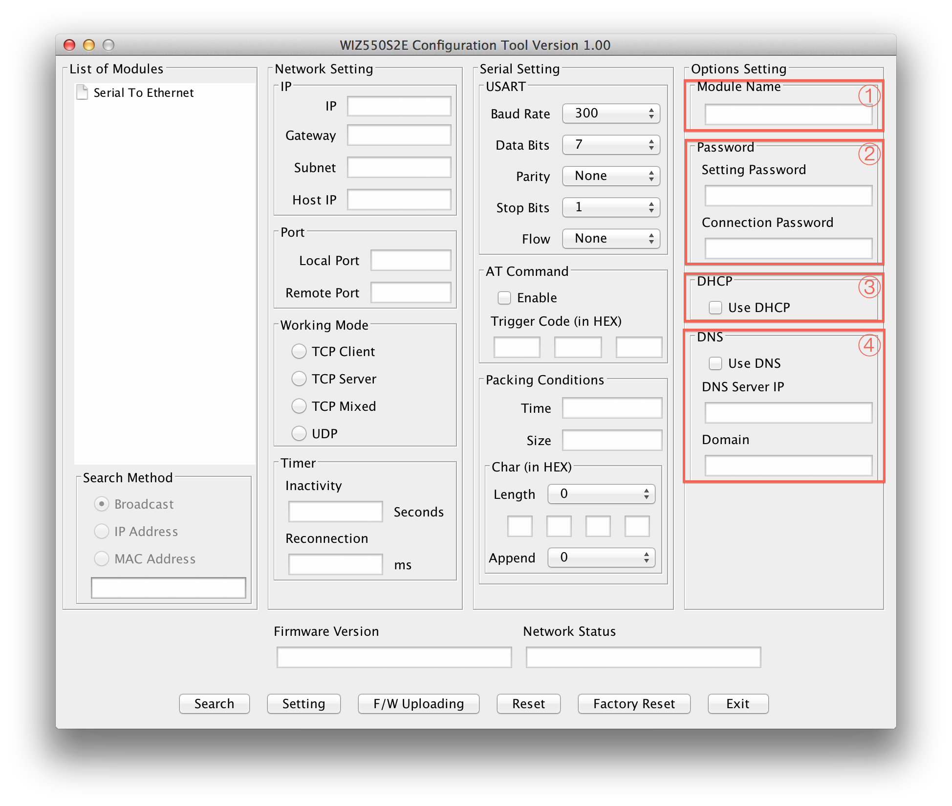
Module Name
The device name is displayed in this area.
User can use this name to distinguish this module with others
Password
This is password field for authentication.
Setting Password : Setting Password for Configuration Tool. Critical functions like "Setting", "Firmware Upload","Reset" and "Factory Reset" need this password to try issued action and avoid unauthorized users' command. When user wants to change its default Setting Password with new one, put new one in this field. Connection Password : When WIZ550SR is TCP server, it needs connection password to check whether TCP client is an unauthorized user or not. After TCP Client is connected, it must transfer correct "Connection Password" within 3 seconds. Otherwise, WIZ550SR will close its TCP connection.
DHCP
This decides how to obtain IP address. If user selects "Use DHCP" then WIZ550SR will obtain IP address dynamically by DHCP operation. Otherwise, it will operate in static mode.
Static mode :
If user uses this mode by deselecting "Use DHCP", user has to set WIZ550SR with specific network information.
- First, select "MAC address" in "Search Windows"
- Then, IP setting section will be activated
- Fill those fields with information which user want to set.
- And press "Setting" button then network information will be changed with value user entered. DHCP mode : WIZ550SR's network information will be set automatically without user's interference.
DNS
This is valid in TCP Client mode only. Normally, TCP Client mode has to know its peer system's IP address. But there are some cases where the IP address is unknown and especially when the IP address change frequently.
In this case, DNS function is needed.
User has to select “Use DNS” option and set DNS Server IP address and peer systems' Domain name in string. Put DNS Server IP, provided by ISP, into “DNS Server IP” field and peer system's Domain name into “Domain” field.