WIZ505SR-RP-EVB
WIZ505SR-RP EVB
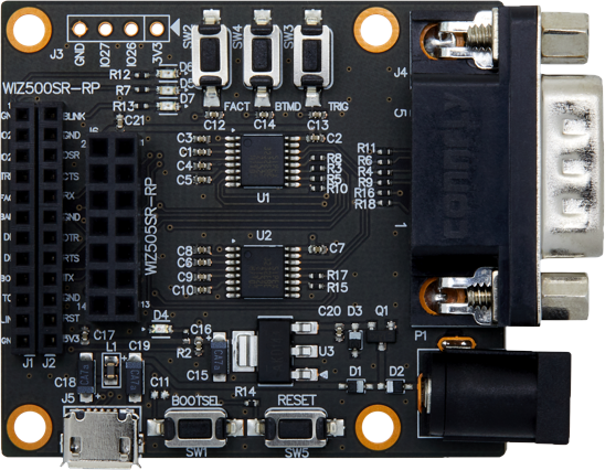 |
| TOP |
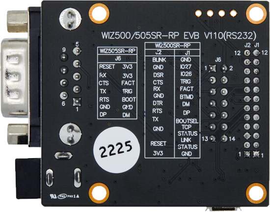 |
| BOTTOM |
Connector Specification
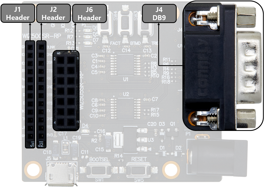
| J1 | Pin Number | Signal | Description |
|---|---|---|---|
| ::: | 1 | GND | System Ground |
| ::: | 2 | LINK STATUS | Link status LED signal input |
| ::: | 3 | TCP STATUS | TCP status LED signal input |
| ::: | 4 | BOOTSEL | BOOTSEL signal output |
| ::: | 5 | USB DP | USB DP signal output |
| ::: | 6 | USB DM | USB DM signal output |
| ::: | 7 | BOOTMODE | BOOTMODE signal output |
| ::: | 8 | FACT RST | Factory reset signal output |
| ::: | 9 | HW TRIG | HW TRIG signal output |
| ::: | 10 | IO26 | Reserved pin |
| ::: | 11 | IO27 | Reserved pin |
| ::: | 12 | GND | System Ground |
| J2 | Pin Number | Signal | Description |
|---|---|---|---|
| ::: | 1 | 3V3 | System Power Output (3.3V) |
| ::: | 2 | RESET | Reset Signal output |
| ::: | 3 | GND | System Ground |
| ::: | 4 | UART1_TX | Transmit Data |
| ::: | 5 | UART1_RTS | Request To Send |
| ::: | 6 | UART1_DTR | Data Terminal Ready |
| ::: | 7 | GND | System Ground |
| ::: | 8 | UART1_RX | Receive Data |
| ::: | 9 | UART1_CTS | Clear To Send |
| ::: | 10 | UART1_DSR | Data Set Ready |
| ::: | 11 | GND | System Ground |
| ::: | 12 | BLINK | Working LED Signal Input |
| J6 | Pin Number | Signal | Description |
|---|---|---|---|
| ::: | 1 | RESET | Reset Signal output |
| ::: | 2 | 3V3 | System Power Output (3.3V) |
| ::: | 3 | UART1_RX | Receive Data |
| ::: | 4 | 3V3 | System Power Output (3.3V) |
| ::: | 5 | UART1_CTS | Clear To Send |
| ::: | 6 | FACT RST | Factory reset signal output |
| ::: | 7 | UART1_TX | Transmit Data |
| ::: | 8 | HW TRIG | HW TRIG signal output |
| ::: | 9 | UART1_RTS | Request To Send |
| ::: | 10 | BOOTSEL | BOOTSEL signal output |
| ::: | 11 | GND | System Ground |
| ::: | 12 | GND | System Ground |
| ::: | 13 | USB DP | USB DP signal output |
| ::: | 14 | USB DM | USB DM signal output |

WIZ500SR-RP indicate

| Ref | Signal | Description |
|---|---|---|
| D4 | Power LED(Red) | Power on LED |
| D5 | TCP_STATUS LED(Green) | ON : Connect OFF : Disconnect |
| D6 | LINK_STATUS LED(Green) | ON : LINK OFF : Unlink |
| D7 | BLINK LED(Green) | Working indicate When Module working well Blinking every 1.0s |
Schematic
WIZ505SR-RP EVB
| H/W version | Type | Filetype | Download Link | Remarks |
|---|---|---|---|---|
| 1.0 | TTL | Altium | - | |
| ::: | ::: | - |
Part list
WIZ505SR-RP EVB
| H/W version | Type | Filetype | Download Link | Remarks |
|---|---|---|---|---|
| 1.0 | TTL | Excel | - | |
| ::: | ::: | - |
Switch Specification

| Ref | Signal | Description |
|---|---|---|
| SW1 | BOOTSEL SW | When push SW1, then BOOTSEL Pin(J1-4pin) will be low |
| SW2 | FACT RST SW | When push SW2, then FACT RST Pin(J1-8pin) will be low |
| SW3 | HW TRIG SW | When push SW3, then HW TRIG Pin(J1-9pin) will be low |
| SW4 | BOOTMODE SW | When push SW4, then BOOTMODE Pin(J1-7pin) will be low |
| SW5 | RESET SW | When push SW5, then RESET Pin(J2-2pin) will be low |