Quickstart Guide
WizFi250 Evaluation Board
The WizFi250 EVB is the evaluation board for testing WizFi250 and prototyping development. WizFi250 EVB is composed of a WizFi250 evaluation board and a WizFi250 module.
Feature Identification
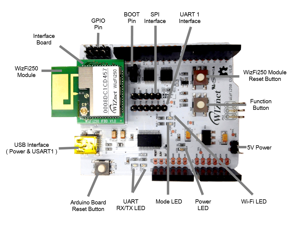
Button Description
| WizFi250 Reset | Through this button, user can restart WizFi250 module. |
|---|---|
| Function | Through the function button, user can enter specific mode without AT Command. ♦ Factory Recovery : When doing Boot or Reset, press the button over 3.5 seconds ♦ AP Mode : When module is working, press it once. ♦ OTA Mode : When module is working, press it twice. ♦ Factory Default : When module is working, press it three times. |
| Arduino Board Reset | With this button, user can restart Arduino board |
LED Description
| UART RX/TX | Indicate UART RX/TX Status |
| Power LED | Indicate Power On/Off of WizFi250 |
| Mode LED | Indicate Data/Command Mode ♦ LOW(ON) : Data Mode ♦ HIGH(OFF) : Command Mode |
| Wi-Fi LED | Indicate Wi-Fi Association ♦ LOW(ON) : Wi-Fi is associated ♦ HIGH(OFF) : Wi-Fi is not associated |
Pin Description
| BOOT | Enter boot mode ♦ SHORT : Start in boot mode ♦ OPEN : Start in application mode |
| 5V Power | Alternative choice for 5V power supply |
| GPIO Pin | Through this pin, user can use GPIO signal |
Interface Description
| UART1 Interface | Alternative choice for Serial interface. |
| SPI Interface | Through these pins, user can control SPI interface. |
| USB Interface | This provides power supply & Serial interface Default serial information: ♦ Baud rate : 115200 ♦ Data rate : 8 ♦ Stop bits : 1 ♦ Parity : None ♦ Flow control : None |
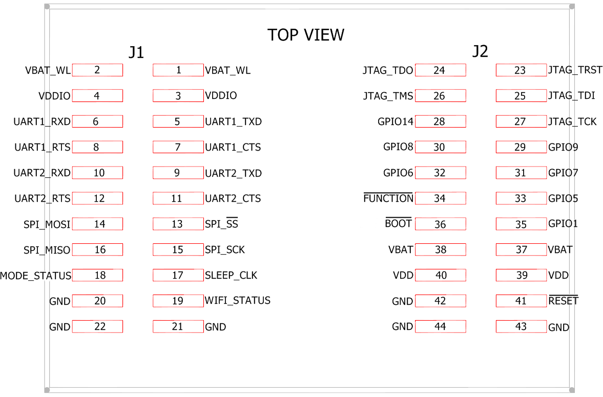
Interface Board PIN Map
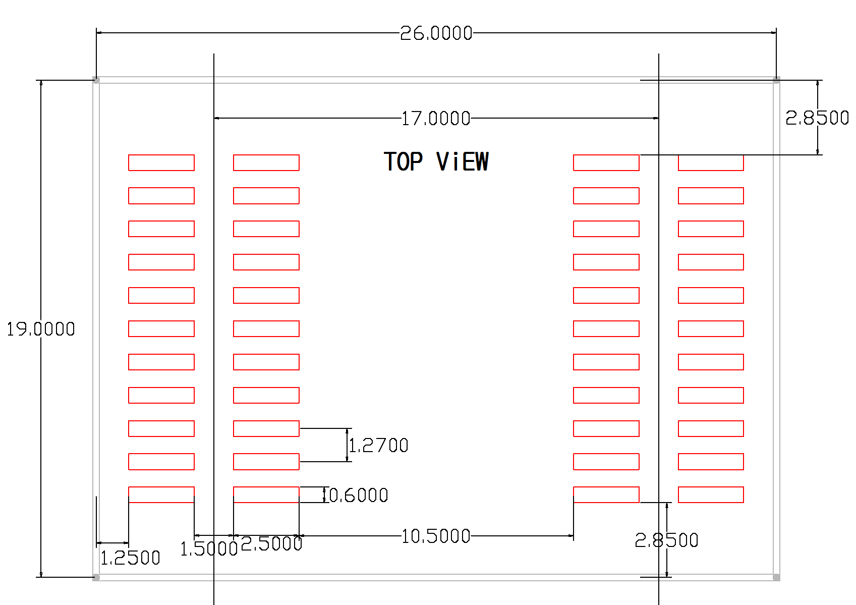
Interface Board Dimension
Stsart Serial to Wi-Fi
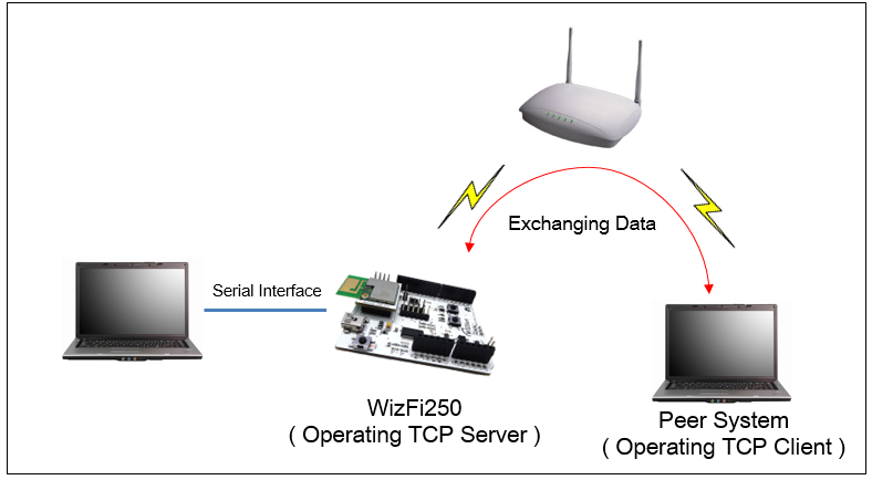
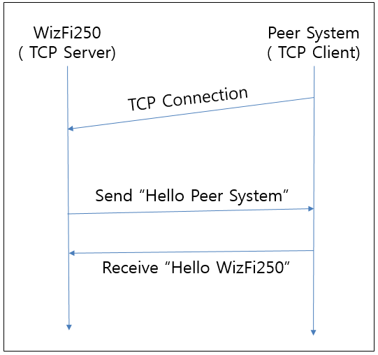
This chapter explains how to set WizFi250 in order to exchange data with peer system. This picture shows the environment for using Serial to Wi-Fi as example. In this example, WizFi250 is set to the TCP server and peer system is set to the TCP client. And then data is exchanged between WizFi250 and the peer system.
Using Function Button & Web Server Interface
This section explains how to set WizFi250 using web server in order to
use serial to Wi-Fi application. (If you Use the function button, you
can launch web server easily.)
Procedure for setting serial to Wi-Fi is explained below.
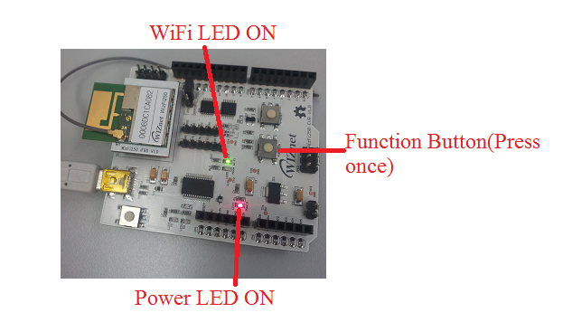
- Press the “Function Button” one time in order to run AP mode and launch the web server. If WizFi250 is changed to AP mode successfully, Wi-Fi LED will be on and you can see WizFi250’s SSID by your PC
| Default information of WizFi250 AP Mode | |
|---|---|
| SSID | WizFi250_AP_0008DCXXXXXX |
| Security | WPA2 Mixed |
| Security Key | 123456789 |
| IP Address | 192.168.12.1 |
| Gateway Address | 192.168.12.1 |
LED results of WIZFI250:
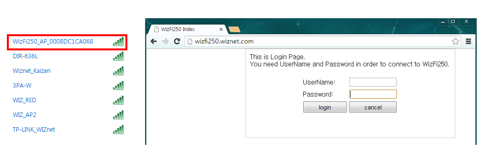
- Connect to WizFi250’s SSID …by inputting default password (123456789) and WizFi250’s IP address or URL (wizfi250.wiznet.com) in your web browser. After that input the user id and user password. ( Default ID : admin, Default Password : admin )
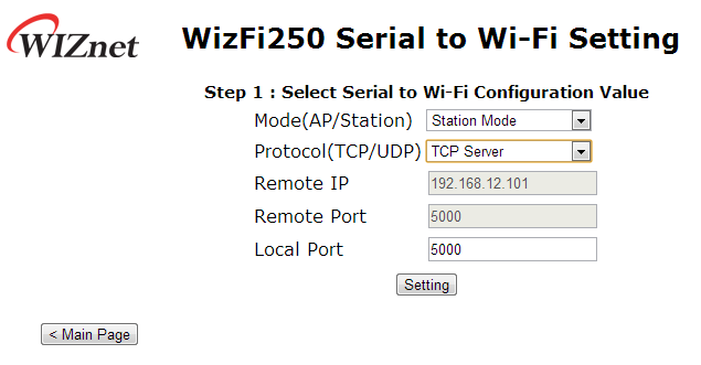
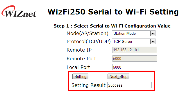
- If you select “S2W Setting & Scan Network” menu, …the web page will be shown as below.\ If WizFi250 is set successfully, it shows the success message … as in the following picture on the right.\ If you select < Next_Step > button, you can move to next page.
| WizFi250 TCP/IP Settings guide | |
|---|---|
| Modes | AP or Station (connect to AP) |
| Protocol | TCP/UDP (Server / Client) |
| Remote IP | Connecting device's IP address |
| Remote Port | Connecting device's Port |
| Local Port | Module's Port |
 |  |
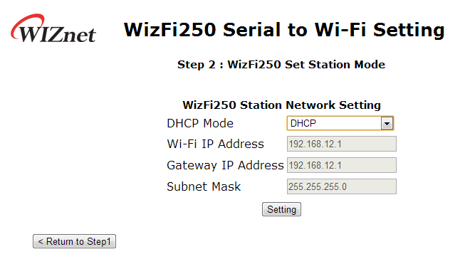
- Select WizFi250's DHCP Mode. \ It includes DHCP or stactic IP setting.
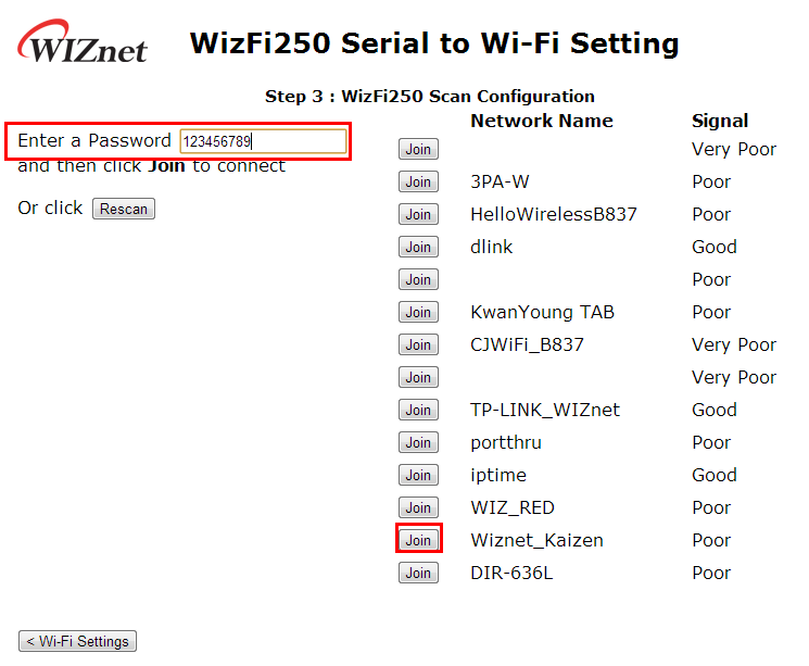
- Firstly, input the password of …the AP you want to join and click “Join“ button to connect to that AP. \ \ After setting up, you will see “Device Started Web server and access point stopped. See UART for further information.” message in web browser. It means that WizFi250 will try to connect to the selected AP.\ \ Important note: If you input the wrong password of AP, you need to redo all procedures.
- WizFi250 will be associated … to the AP you select… and you can use TCP server in WizFi250.\ This picture is the serial message when WizFi250 has set successfully.

Using Serial Command
This section explains how to connect to AP by using serial command.
The module start by default in command mode. If the user inputs the AT
commands below, WizFi250 will be connected to AP by DHCP and run as TCP
server.
In this example, the settings of AP will be created as below:
( SSID : WizFiDemoAP, Security : WPA2, Key : 12345678 )
AT (Sent AT command with 0x0d (Hex of Enter button)) [OK] (response meaning successful execution)
AT+WSET=0,WizFiDemoAP (AT command for setting WiFi association) [OK]
AT+WSEC=0,,12345678 (AT command for setting WiFi security) [OK]
AT+WNET=1 (AT command for setting DHCP) [OK]
AT+WJOIN (AT command executing AP association) Joining : WizFiDemoAP Successfully joined : WizFiDemoAP
[Link-Up Event] IP Addr : 192.168.3.104 Gateway : 192.168.3.1 [OK]
AT+SCON=SO,TSN, , ,5000,1 (AT command for setting TCP Server) [OK]
[CONNECT 0] (When TCP connection is done, it shows this message)
Now, the green mode LED is on, and data can be exchanged from Serial I/F
to connected client and back. This mode is called data mode.
To exit this data mode or to enter into command mode again you need to
send a single '+++' string without CR or LF (0x0D, 0x0A) - just the
three 0x2B = '+' characters.
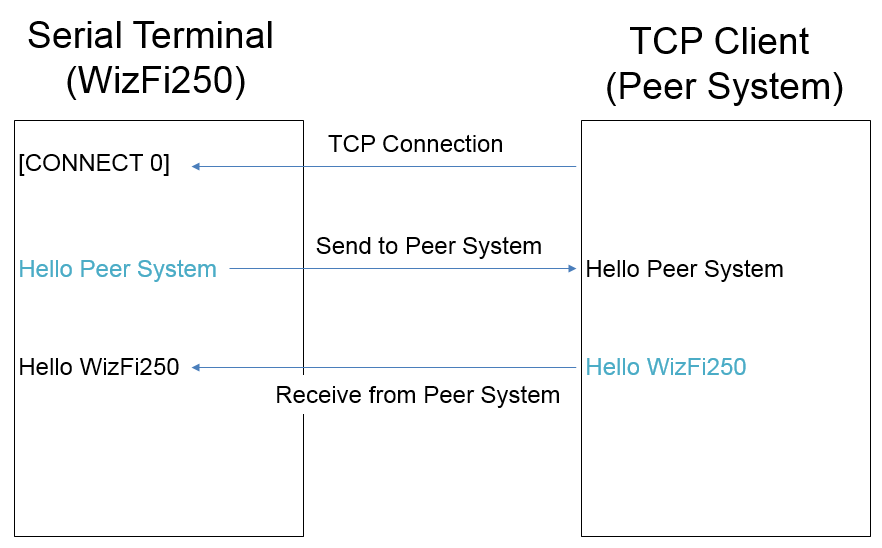
Exchanging data with a peer system
This section explains how to exchange data between WizFi250 and Peer
System.
This example describes the structure of data flow.
After TCP connection is done and if WizFi250 receives serial data, the
serial data will be sent to peer system immediately and Wizfi250 can
receive data from peer system.