Programmer's guide
Overview
This document provides programmers with all commands and explanations about WizFi250 control. Basically programmers can control WizFi250 with commands set, known as AT command – the character string format. In this document, we describe what AT commands are used, how each command operates and how programmers have to handle those commands to get the expected response.
AT Command Set
This section provides a list of WizFi250 AT commands and their effects. Users can input commands and parameters through USART line. Every command starts with the characters “AT”. Any other initial character will cause an error in return. Commands and parameters are all ASCII characters, e.g. When you input 'AT+MMSG=1', you can input ASCII characters 'A', 'T', '+', 'M', 'M', 'S', 'G', '=', '1' and 'Enter Key' which should be CR(0x0d), but neither CRLF(0x0d, 0x0a) nor LF(0x0a).
Some parameters are mandatory and the others are optional. (refer to Command Tables) Parameters must be entered in an order of format column given by the command tables. Even though an optional parameter is not used, the comma delimiters must still be included in the command. In most cases, valid commands return the characters [OK]. Invalid inputs return [ERROR]. The possible responses sent by WizFi250 to the user side are described at Responses. Below is a possible example which users can input. As you can see, WizFi250 return "\r\n" back instead of "\r", which means user (host system) always handle '\r\n' as a only delimiter.
| input by user | AT\r (0x61 0x74 0x0d) |
|---|---|
| Output from WizFi250 | AT\r\n[OK]\r\n (0x0d 0x0a 0x5b 0x4f 0x4b 0x5d 0x0d 0x0a)(* “AT\r\n” is Echo back of user input) |
Responses
Responses are listed below.
| Response | Meaning |
|---|---|
| [OK] | Command Request Success |
| [ERROR] | Command Request Fail |
| [ERROR: INVALID INPUT] | Wrong command or parameter |
| [ERROR: INVALID SCID] | Wrong Socket ID |
| [ERROR: WiFi Status] | Wrong WiFi Status (Some commands work only with Wi-Fi Joined status) |
| [ERROR: Mode Status] | Wrong Mode Status (Some commands do not work in Data mode) |
| [CONNECT x] | TCP Connection established & Socket Open |
| [DISCONNECT x] | TCP Connection closed & Socket Close |
| [Link-Up Event] | WiFi Connection was established |
| [Link-Down Event] | WiFi Connection was closed |
| [Reset Event] | System reset occurred (not by user) |
Command list
| Basic Commands | |
|---|---|
| AT | Terminal Check |
| WiFi Commands | |
| AT+WJOIN | WiFi Association |
| AT+WLEAVE | WiFi Disassociation |
| AT+WSCAN | WiFi Scan |
| AT+WSET | WiFi Configuration |
| AT+WSEC | WiFi Security Configuration |
| AT+WNET | Network Configuration |
| AT+WSTAT | Get Current WiFi Status |
| AT+WREG | Country Configuration |
| AT+WWPS | WiFi WPS Connection |
| AT+WANT | WiFi Antenna Configuration |
| AT+WP2P_START | Start WiFi Direct |
| AT+WP2P_STOP | Stop WiFi Direct |
| AT+WP2P_PEERLIST | Get WiFi Direct peer list |
| AT+WP2P_INVITE | Invite WiFi Direct peer ID |
| AT+WCHECK | Check Wi-Fi status using Ping and Re-association with AP |
| Network Commands | |
|---|---|
| AT+SCON | Socket Open/Connect |
| AT+SMGMT | Socket Management |
| AT+SSEND | Data Send |
| AT+SDATA | Return to Data Mode |
| AT+SFORM | Define Data Receive Header Form |
| Management Commands | |
|---|---|
| AT+MPROF | Profile Management |
| AT+MFDEF | Perform Factory Reset |
| AT+MRESET | Perform System Reset |
| AT+MMSG | Set Message Print Level |
| AT+MMAC | Set MAC Address |
| AT+MINFO | Get System Information |
| AT+MECHO | Set Echo Mode |
| AT+MHELP | Print Command Description and Usage |
| AT+MMCUPS | MCU Power Save Enable/Disable |
| AT+MWIFIPS | Wi-Fi Power Save Enable/Disable |
| AT+MCWUI | Change WebServer User Information |
| AT+USET | UART Configuration |
| AT+MSPI | SPI Configuration |
| AT+MAIRCMD | Air Command Configuration |
| AT+MEVTMSG | Print [Listen x] as soon as it opens up a socket through TCP server. |
| AT+MEVTFORM | Event Message Form |
| Function Commands | |
|---|---|
| AT+FPING | PING Test |
| AT+FDNS | DNS Query |
| AT+FWEBS | Launch Web Server |
| AT+FGPIO | GPIO Control |
| AT+FSOCK | SOCKET Extension Option |
| AT+FOTA | Launch OTA Mode |
Basic Commands
Basic commands are listed below.
AT
- Format:
AT
- Meaning: Terminal Check
Check if AT Command Terminal is working.
- Response:
[OK]
WiFi Commands
Commands related to WiFi are listed below.
AT+WJOIN
- Format:
AT+WJOIN
- Meaning: WiFi Association
In the STA mode, it joins with the BSS selected by AT+WSET, AT+WSEC.
And in the AP mode, it starts to run as an Access Point.
- There are 2 Wi-Fi modes in WizFi250, STA mode and SoftAP mode. When users execute AT+WJOIN command, the current Wi-Fi mode works as the one previously selected by user input. It can be selected or checked by AT+WSET and AT+WSEC commands, and it is the only way to handle Wi-Fi mode.
- SoftAP mode does not support WEP security method.
- Response:
Joining : (SSID)
Successfully joined : (SSID)

[Link-Up Event]
IP Addr    : xxx.xxx.xxx.xxx
Gateway   : xxx.xxx.xxx.xxx
[OK]
Already Associated :
(Mode)
[OK]
AT+WLEAVE
- Format:
AT+WLEAVE
- Meaning: WiFi Disassociation
In the STA mode, it leaves current BSS, but in the SoftAP mode, it stops to run as Access Point.
- Response:
[Link-Down Event]
[OK]
[OK]
AT+WSCAN
- Format:
AT+WSCAN=<SSID>,<BSSID>,<Channel>
- Meaning: WiFi Scan
Return the scan results filtered by parameters.
<SSID>: SSID Filter (Optional)
Scan only the AP which has this SSID.
<BSSID>: BSSID Filter (Optional)
Scan only the AP which has this BSSID.
<Channel>: Channel Filter (Optional)
Scan only the AP in this Channel.
When combining these filters, it works at the same time. For example, if you enter AT+WSCAN=TestAP,00:08:DC:11:22:33', it only scans the AP which has TestAP as SSID and 00:08:DC:11:22:33 as BSSID in all the channel.
Examples)
  * AT+WSCAN=TestAP
  * AT+WSCAN=,,6
  * AT+WSCAN=,08:00:DC:11:22:33,11
-
Response:
Index/SSID/BSSID/RSSI(-dBm)/MaxDataRate(Mbps)/Security/RadioBand (GHz)/Channel ... [OK]
AT+WSET
- Format:
AT+WSET=<WiFiMode>,<SSID>,<BSSID>,<Channel>
- Meaning: WiFi Configuration
<WiFiMode>: WiFi Mode to set (Required)
This changes current WiFi mode.
| Parameter | Meaning |
|---|---|
| 0 | Set Wi-Fi mode as STA mode |
| 1 | Set Wi-Fi mode as AP mode |
<SSID>: Target/Own SSID (Required, Max: 32 Character)
| Mode | Meaning |
|---|---|
| STA | The SSID of target AP |
| AP | Its own SSID to run |
<BSSID>: Target BSSID (Optional, Form: xx:xx:xx:xx:xx:xx)
| Mode | Meaning |
|---|---|
| STA | The BSSID of target AP |
| AP | Not used. if any, it will be ignored |
<Channel>: Target/Own Channel (Optional)
| Mode | Meaning |
|---|---|
| STA | In STA mode, the Channel of target AP |
| AP | In AP mode, its own Channel to run (Default: 6) |
* There are 2 Wi-Fi modes in WizFi250, STA mode and SoftAP mode. When users execute AT+WJOIN command, it works as Wi-Fi mode previously selected by the user. It can be selected or checked by AT+WSET and AT+WSEC commands, and it is the only way to handle Wi-Fi mode.
* AT+WSET, AT+WSEC commands save its parameters into the profile automatically, so the user does not need to save the current profile.
Examples)
  * AT+WSET=0,WizFiAP
  * AT+WSET=0,WizFiAP,08:00:DC:11:22:33,1
-
Response:
[OK]
-
Format:
AT+WSET=?
-
Meaning: Get Current Setting
-
Response:
<WiFiMode>,<SSID>,<BSSID>,<Channel>
[OK]
AT+WSEC
- Format:
AT+WSEC=<WiFiMode>,<SecType>,<Key>
- Meaning: WiFi Security Configuration
<WiFiMode>: Target WiFi mode to set (Required)
| Parameter | Meaning |
|---|---|
| 0 | Set Wi-Fi mode as STA mode |
| 1 | Set Wi-Fi mode as AP mode |
<SecType>: Security type (Optional)
| Parameter | Meaning |
|---|---|
| OPEN | None |
| WiFi Auto Security | |
| WEP | WEP (* Not support at SoftAP mode) |
| WPA | WPA1 - TKIP |
| WPAAES | WPA1 - AES |
| WPA2AES | WPA2 - AES |
| WPA2TKIP | WPA2 - TKIP |
| WPA2 | WPA2 - Mixed |
<Key>: Security key value
| Method | Length |
|---|---|
| WEP | 5 or 13 (ASCII), 10 or 26 (HEX) |
| WPA | 8 ~ 63 (ASCII), 128 (HEX) |
* There are 2 Wi-Fi modes in WizFi250, STA mode and SoftAP mode. When users execute AT+WJOIN command, it works as Wi-Fi mode previously selected by the user. It can be selected or checked by AT+WSET and AT+WSEC commands, and it is the only way to handle Wi-Fi mode.
* AT+WSET, AT+WSEC commands save its parameters into the profile automatically, it works as Wi-Fi mode previously selected by the user.
* Minimum key length is 8 bytes in WiFi Auto Security.
In case of WEP mode and 5 bytes key, you should input the key with HEX type.
AT+WSEC=0,,12345(X)
AT+WSEC=0,,3132333435(O)
In case of OPEN mode, you should input the 8 bytes dummy string. Then WizFi250 will ignore the dummy key in OPEN mode.
AT+WSEC=0,,(X)
AT+WSEC=0,,12345678(O)
Examples)
  * AT+WSEC=0,WEP,12345
  * AT+WSEC=1,WPA2,12345678
  * AT+WSEC=0,,123456789\\ \\
- Response:
[OK]
-
Format:
AT+WSEC=?
-
Meaning: Get Security Setting of Current Mode
-
Response:
<WiFiMode>,<SecType>,<Key>
[OK]
AT+WNET
- Format:
AT+WNET=<DHCP>,<IP>,<SN>,<GW>
- Meaning: Network Configuration
<DHCP>: DHCP On/Off (Optional)
| Parameter | Meaning |
|---|---|
| 0 | DHCP Off, Static |
| 1 | DHCP On, DHCP Client |
| Mode | Meaning |
| STA | DHCP Client On/Off |
| AP | Not used. if any, it will be ignored |
<IP>: IP Address (Optional)
<SN>: Subnet Mask (Optional)
<GW>: Gateway Address (Optional)
| Mode | Meaning |
|---|---|
| STA | AP(Router) gateway address |
| AP | Not used. if any, it will be ignored |
* When you turn DHCP On in STA Mode, <IP>,<SN>,<GW> are not needed. If you input them at this time, they will be stored in the memory. They can be used later when set as Static(DHCP Off) without inputting these parameters.
* In AP mode, DHCP Server will always run despite DHCP option, and Gateway option will not be used, So both options will be ignored.
- Response:
[OK]
- Format:
AT+WNET=?
- Meaning: Get Current Network Setting
Note that <IP>,<SN>,<GW> address of response are not actual addresses, but addresses stored in the memory. So when DHCP is on, it usually different from actual addresses.
- Response:
<DHCP>,<IP>,<SN>,<GW>
[OK]
AT+WSTAT
- Format:
AT+WSTAT
-
Meaning: Get Current WiFi Status
-
Response:
IF/SSID/IP-Addr/Gateway/MAC/TxPower(dBm)/RSSI(-dBm)
...
[OK]
AT+WREG
- Format:
AT+WREG=<Country>
- Meaning: Country Configuration
Input a two letter country code (ISO 3166-1 A2) like US.
-
Response:
[OK]
-
Format:
AT+WREG=?
-
Meaning: Get Current Country Setting
Refer to ISO 3166-1 A2
- Response:
<Country>
[OK]
AT+WWPS
- Format:
AT+WWPS=<Mode>,<PinNum>
- Meaning: WiFi WPS Connection
Join with an AP through WPS method
<Mode>: WPS Mode (Required)
| Parameter | Meaning |
|---|---|
| 0 | WPS_PBC_MODE |
| 1 | WPS_PIN_MODE |
<PinNum>: Pin Number (Pin Mode: Required, PBC Mode: N/A)
* The maximum pin number letter is 8.
Examples)
  * AT+WWPS=0
  * AT+WWPS=1,12345670
-
Response:
[OK]
AT+WANT
- Format:
AT+WANT=<Antenna type>
- Meaning: WiFi Antenna Configuration
You had better not use this command unless it's absolutely necessary.
<Mode>: WiFi Antenna Type (Required)
| Parameter | Meaning |
|---|---|
| 0 | u.FL Antenna |
| 1 | PCB Antenna |
| 3 | Auto Selection |
-
Response:
[OK]
-
Format:
AT+WANT=?
-
Meaning: Get Current WiFi Antenna Type
-
Response:
<Antenna Type>
[OK]
AT+WP2P_START
- Format:
AT+WP2P_START
-
Meaning: Start WiFi Direct
-
Response:
STA MAC: CE:52:AF:C6:CF:B5 [OK]
AT+WP2P_STOP
- Format:
AT+WP2P_STOP
-
Meaning: Stop WiFi Direct
-
Response:
[OK]
AT+WP2P_PEERLIST
- Format:
AT+WP2P_PEERLIST
-
Meaning: Get WiFi Direct peer list
-
Response:
P2P Peers:
0: 'SHV-E250S' on channel 1
[OK]
AT+WP2P_INVITE
- Format:
AT+WP2P_INVITE=<Peer ID>
- Meaning: Invite WiFi Direct peer ID
<Peer ID>: Peer ID to invite. This is from <AT+WP2P_PEERLIST> command.(Required)
-
Response:
[OK]
AT+WCHECK
- Format:
AT+WCHECK=<time>,<ping try>,<ping error>
- Meaning: Check Wi-Fi status using Ping and Re-association with AP
It must be set as service mode in order to use Re-association function.
This function only exist later vision of F/W 1.0.3.5.
To use this option, you must enter a non-zero value.
<time>: try to ping (to gateway) each time. 10 ~ 86400(required, unit:sec)
<ping try>: count of ping. 5 ~ 20(required, unit:number of times)
<ping error>: WizFi250 will be disassociated if ping timeout is more than this. 1 ~ 20(required, unit:number of times)
Examples)
  * AT+WCHECK=0,0,0 (Not in use)
  * AT+WCHECK=60,5,3 (Recommended. WizFi250 will try to ping to the gateway every 60 seconds. If ping timeout is more than 3, it would be disassociated.)
-
Response:
[OK]
AT+WADNS
- Format:
AT+WADNS=<DNS Server1>,<DNS Server2>
- Meaning: Add DNS Server
<DNS Server 1>: DNS Server 1
<DNS Server 2>: DNS Server 2
Examples)
* AT+WADNS=8.8.8.8
-
Response:
[OK]
Network Commands
Commands related to Network are listed below.
AT+SCON
- Format:
AT+SCON=<OpenType>,<SocketType>,<RemoteIP>,<RemotePort>,<LocalPort>,<DataMode>
- Meaning: Socket Open/Connect ( User can use max 8 sockets. )
Opens a socket and if it is a TCP Client, establishes TCP connection with remote peer device.
<OpenType>: Socket open type (Required)
| Parameter | Meaning |
|---|---|
| O | open at Once |
| S | register as a Service |
| SO | open at Once & register as a Service |
* AT ONCE: Assigns a socket immediately and if the socket is a TCP Client, tries to connect peer socket.
* AS SERVICE: Registers its information to the profile. When WiFi Joined, socket open/connect will be performed automatically. If you want to use this after reset, It should be saved by using AT+MPROF=S.
<SocketType>: Socket protocol to use (Required)
| Parameter | Meaning |
|---|---|
| TSN | TCP Server Normal |
| TSS | TCP Server Secured |
| TCN | TCP Client Normal |
| TCS | TCP Client Secured |
| USN | UDP Server Normal |
| UCN | UDP Client Normal |
* 'Secured' means TCP connection through SSL Encryption.
* Actually, there is no Server/Client concept in UDP protocol. This concept is used to decide peer address purposes. If a UDP Server receives any packet, its default peer address will be changed to the address of the packet, so if you send data after that, it goes to the changed address. But If you use UDP Client, its …default address stored by AT+SCON will never be changed.
<RemoteIP>: Remote IP address
| Protocol | Parameter Application |
|---|---|
| TCP Server | N/A |
| TCP Client | Required |
| UDP Server | Optional |
| UDP Client | Required |
<RemotePort>: Remote port number
Same condition with upper, RemoteIP
<LocalPort>: Local port number (Required)
Local port number should not be duplicated with others which have opened before. When the value is 0, in case the socket was a TCP/UDP Client, a random port number will be selected. If it was a TCP/UDP Server, it will return an error message.
<DataMode>: Mode to run (Optional, default: 0)
| Parameter | Meaning |
|---|---|
| 0 | Open as Command mode |
| 1 | Open as Data mode |
* About Command/Data mode, refer to [Command mode & Data mode]
Examples)
  * AT+SCON=O,TSN,,,5000,0
  * AT+SCON=S,UCN,192.168.0.10,12345,5000,1 (Profile must be saved)
-
Response:
[OK]
-
Format:
AT+SCON=?
-
Meaning: Get Previous Input Parameters
Use for check if previous input parameters are correct.
- Response:
<OpenType>,<SocketType>,<RemoteIP>,<RemotePort>,<LocalPort>,<DataMode>
[OK]
AT+SMGMT
- Format:
AT+SMGMT=<SocketID>
- Meaning: Socket Management - Socket Close
Closes the selected socket and releases all its resources.
<SocketID>: Socket ID (Required)
| Parameter | Meaning |
|---|---|
| 0 ~ 7 | The socket ID to close |
| ALL | All the opened sockets |
* Opened socket information can be found by using '?' option.
Examples)
  * AT+SMGMT=5
  * AT+SMGMT=ALL
-
Response:
[OK]
-
Format:
AT+SMGMT=?
-
Meaning: Socket Management - Get Opened Socket Status
This prints all of the opened sockets statuses.
- Response:
Number of Sockets : x (SCID/Socket/Mode/Remote/Local/DataMode)
<SocketID>,<SocketAddr>,<SocketType>,<RemoteIP>,<RemotePort>,<LocalPort>,<DataMode>
...
[OK]
AT+SSEND
- Format:
AT+SSEND=<SocketID>,<RemoteIP>,<RemotePort>,<SendSize>,<Timeout>
- Meaning: Data Send
This is used only in command mode, not in data mode. It is not required in data mode as you can input directly, but if you exit from data mode to command mode by inputting '+++', you can send data through this command.
<SocketID>: Socket ID (Required)
<RemoteIP>: Remote IP Address
| Protocol | Parameter Application |
|---|---|
| TCP Server | N/A |
| TCP Client | N/A |
| UDP Server | Optional |
| UDP Client | Optional |
* In case of TCP Server waiting for a client on listen state or in case of undecided remote address of the UDP Server (meaning its remote address is 0.0.0.0:0), this command will fail.
<RemotePort>: Remote Port Number
Same condition with upper, RemoteIP
<SendSize>: Data size to send (Required)
Valid Range: 1 ~ 100,000,000 Byte
<Timeout >: Set timeout value (milliseconds unit) (Optional)
If the transmission takes time more time than timeout value, it will fail and return error response. Default value is 10s + (100s / 1 MB)
Examples)
  * AT+SSEND=0,,,3
  * AT+SSEND=1,192.168.0.100,5000,1000000,50000
-
Response:
[OK]
AT+SDATA
- Format:
AT+SDATA
- Meaning: Return to Data Mode
In data mode, it can be changed to command mode temporally by using serial '+++' input. After that, to return to the data mode, you can use this command. If it is not data mode, [ERROR] response will be returned.
-
Response:
[OK]
AT+SFORM
- Format:
AT+SFORM=<Format>,<Start>,<Delim>,<End>,<Cls1>,<Cls2>
- Meaning: Define Data Receive Header Form
Define the header of received data which is used at command mode. For example, default receiving format look like below.
"{0,192.168.0.216,59834,5}hello(0xd)(0xa)"
This means ASCII code "hello" was received from 192.168.0.216:59834 by socket ID 0, and its length was 5. You can change this format to suit your system through this command. Factory default option is "111111111,7B,2C,7D,0D,0A"
<Format>: Decide each of header items to use. (Required)
If you want to set it to active, input '1', if not, input '0'.
| Order | Meaning |
|---|---|
| 0 | Header Start |
| 1 | Socket ID |
| 2 | Delimiter |
| 3 | Remote IP Address |
| 4 | Remote Port Number |
| 5 | Data Length |
| 6 | Header End |
| 7 | Data End 1/2 |
| 8 | Data End 2/2 |
* At default format, ' ' is header start and end, ',' is delimiter, 0xd,0xa is data end 1,2.
< Start>: Header Start Character (Required)
< Delim>: Delimiter Character (Required)
< End>: Header End Character (Required)
< Cls1>: Data End Character 1/2 (Required)
< Cls2>: Data End Character 2/2 (Required)
Examples)
  * AT+SFORM=111111111,7B,2C,7D,0D,0A
  * AT+SFORM=101100110,5B,2F,5D,0D,00
-
Response:
[OK]
-
Format:
AT+SFORM=?
-
Meaning: Get Current Data Receive Header Form
-
Response:
<Format>,<Start>,<Delim>,<End>,<Cls1>,<Cls2>
[OK]
AT+SOPT1
- Format:
AT+SOPT1=<Option>,<Value>
- Meaning: S2W miscellaneous option
<Option>: Option to configure (Required) <Value>: Value of the option (Required)
| Option | Value |
|---|---|
| 10 | Escape sequence(+++) Timer(millisecond, default 1000, 1~10000) |
Examples)
* AT+SOPT1=10,500
-
Response:
[OK]
Management Commands
Commands related to system management are listed below.
AT+MPROF
- Format:
AT+MPROF=<Action>
- Meaning: Profile Management
You can save/load the environmentalinformation in the RAM to/from flash ROM, or check the setting values in both of them through this command.
<Action>: The action to perform (Required)
| Parameter | Meaning |
|---|---|
| VD | Get saved profile |
| VG | Get current profile |
| L | Load profile |
| S | Save profile |
* There is no '?' option at this command.
Examples)
* AT+MPROF=S
-
Response:
[OK]
+WSET=... +WSEC=... +WNET=... +WREG=... +SCON=... +SFORM=... +MMSG=... +MMAC=... +USET=... +MECHO=... +FWEBS=... [OK]
AT+MFDEF
- Format:
AT+MFDEF=FR
- Meaning: Perform Factory Reset
Factory Reset means that all of environmental variables return back to the default state. (You can check that by using AT+MPROF command)
-
Response:
[OK]
AT+MRESET
- Format:
AT+MRESET
- Meaning: Perform System Reset
System will reboot after this command.
-
Response:
[OK]
AT+MMSG
- Format:
AT+MMSG=<Level>
- Meaning: Set Message Print Level
<Level>: Message Print Level (Required)
| Parameter | Meaning |
|---|---|
| 1 | Not Print Responses |
| 2 | Print Responses, Events (Default) |
| 3 | Print Responses, Events, Debug Logs |
Examples)
* AT+MMSG=2
-
Response:
[OK]
-
Format:
AT+MMSG=?
-
Meaning: Get Current Message Print Level
-
Response:
<Level>
[OK]
AT+MMAC
- Format:
AT+MMAC=<MAC>
- Meaning: Set MAC Address
<MAC>: MAC Address (separated by colon) (Required)
Examples)
* AT+MMAC=00:08:DC:11:22:33
-
Response:
[OK]
-
Format:
AT+MMAC=?
-
Meaning: Get Current MAC Address
-
Response:
<MAC>
[OK]
AT+MINFO
- Format:
AT+MINFO
-
Meaning: Get System Information
-
Response:
FW version / HW version
<FWver> / <HWver>
[OK]
AT+MECHO
- Format:
AT+MECHO=<Action>
- Meaning: Set Echo Mode
If you turn the echo mode off, you cannot see the characters that you inputted returning. It is easy to use to turn off when Host MCU handles AT Command control.
<Action>: Echo Mode (Required)
| Parameter | Meaning |
|---|---|
| 0 | Echo Off |
| 1 | Echo On (Default) |
Examples)
* AT+MECHO=0
-
Response:
[OK]
-
Format:
AT+MECHO=?
-
Meaning: Get Current Echo Mode
-
Response:
<Mode>
[OK]
AT+MHELP
- Format:
AT+MHELP
- Meaning: Print Command Description and Usage
This is command usage guide for user convenience.
-
Response:
... [OK]
AT+MMCUPS
- Format:
AT+MMCUPS=<Action>,<Timeout>
- Meaning: MCU Power Save Enable/Disable
MCU Power Save Mode can be selected through this command.
<Action> : MCU Power Save Mode (Required)
| Parameter | Meaning |
|---|---|
| 0 | MCU Power Save Mode Disable |
| 1 | MCU Power Save Mode Enable |
* while using MCU Power Save Mode, WizFi250 cannot use serial communication.
<Timeout> : MCU Power Save Timeout value (Required)
Valid Range : 10 ~ 3600000 (unit:ms)
cc
-
Response:
[OK]
AT+MWIFIPS
- Format:
AT+MWIFIPS=<Action>,<Delay>
- Meaning: Wi-Fi Power Save Enable/Disable
Wi-Fi power save mode can be selected through this command.
<Action> : Wi-Fi Power Save Mode (Required)
| Parameter | Meaning |
|---|---|
| 0 | Wi-Fi Power Save Mode Disable |
| 1 | Wi-Fi Power Save Mode Enable |
| 2 | Enables power save mode while attempting to maximize throughput |
* To using Wi-Fi Power Save Mode, WizFi250 has to connect to Access Point. And WizFi250 can only use this mode in station mode.
<Delay > : Return to Sleep Delay
If it is set with a bigger value, the performance will improve but the power consumption will rise.
| Action | Application |
|---|---|
| 0 | N/A |
| 1 | N/A |
| 2 | Required |
* This parameter is used only to set 2 of <Action> parameter.
* It must be set to a multiple of 10. When set to 0, the timeout period default to 2 beacon intervals (approximately 204ms).
* It can be set to 0 ~ 90
-
Response:
[OK]
-
Format:
AT+MWIFIPS=?
-
Meaning: Get Current Wi-Fi Power Save Status
<Status > : Current Wi-Fi Power Save Status
| Return value | Meaning |
|---|---|
| 0 | Wi-Fi Power Save Mode Disable |
| 1 | Wi-Fi Power Save Mode Enable |
-
Response:
[OK]
AT+MCWUI
- Format:
AT+MCWUI=<Current ID>,<Current P/W><New ID>,<New P/W>
- Meaning: Change Web Server's User Information
User ID and User Password used by web server can be changed through this command
<Current ID> : Current ID (Required)
* Default value is admin
<Current P/W> : Current Password (Required)
* Default value is admin
<New ID> : New ID which you want to change (Required)
* Max length of New ID : 20 bytes
<New P/W> : New Password which you want to change (Required)
* Max length of New Password : 20 bytes
Examples)
* AT+MCWUI=admin,admin,newid,newpassword
-
Response:
[OK]
-
Format:
AT+MCWUI=?
-
Meaning: Get Current user ID and user P/W
-
Response:
<Current ID>,<Current P/W>
[OK]
AT+USET
- Format:
AT+USET=<Baudrate>,<Parity>,<WordLen>,<StopBit>,<FlowCon>
- Meaning: UART Configuration
UART parameter can be set through this command. Factory default parameter is "115200,N,8,1,N ".
<Baudrate>: Set the Baud-Rate. (Required)
| Parameter | Meaning |
|---|---|
| 300 | 300 bps |
| 600 | 600 bps |
| 1200 | 1200 bps |
| 2400 | 2400 bps |
| 4800 | 4800 bps |
| 9600 | 9600 bps |
| 14400 | 14400 bps |
| 19200 | 19200 bps |
| 38400 | 38400 bps |
| 57600 | 57600 bps |
| 115200 | 115200 bps |
| 230400 | 230400 bps |
| 460800 | 460800 bps |
| 921600 | 921600 bps |
| 1843200 | 1843200 bps |
<Parity>: Set the Parity-Bit type. (Required)
| Parameter | Meaning |
|---|---|
| N | None |
| O | (Reserved) |
| E | (Reserved) |
<WordLen>: Set the Word-Length. (Required)
| Parameter | Meaning |
|---|---|
| 7 | (Reserved) |
| 8 | 8 bits |
* 7 bits word length with no parity bit is not allowed.
<StopBit>: Set the Stop-Bit. (Required)
| Parameter | Meaning |
|---|---|
| 0.5 | 0.5 bits |
| 1 | 1 bits |
| 1.5 | 1.5 bits |
| 2 | 2 bits |
<FlowCon>: Set the Flow-Control method. (Required)
| Parameter | Meaning |
|---|---|
| N | None |
| HW | Hardware Flow Control |
Examples)
  * AT+USET=115200,N,8,1,N
  * AT+USET=921600,N,8,2,HW
-
Response:
[OK]
-
Format:
AT+USET=?
-
Meaning: Get Current UART Setting
-
Response:
<Baudrate>,<Parity>,<WordLen>,<StopBit>,<FlowCon>
[OK]
AT+MSPI
- Format:
AT+MSPI=<Interface>,<SPI Option>
- Meaning: SPI Configuration
<Interface>: Choice of interface
(Required)
If <Interface> set 0, WizFi250 Will set the interface it received first. For example, If MCU sends UART signal to WizFi250, WizFi250 will be set as UART interface. On the other hand, If MCU send SPI signal to WizFi250, WizFi250 will be set as SPI interface.
| Parameter | Meaning |
|---|---|
| 0 | Auto(Default) |
| 1 | UART |
| 2 | SPI |
<SPI Option>: Configure SPI Option (Optional when use SPI)
| Value | Bit3 | Bit2 | Bit1 | Bit0 |
|---|---|---|---|---|
| 0 | LSB_FIRST | CLOCK_IDLE_LOW | CLOCK_FALLING_EDGE | |
| 1 | MSB_FIRST | CLOCK_IDLE_HIGH | CLOCK_RISING_EDGE |
Examples(Received through UART interface):
* **AT+MSPI=1,0** (SET UART Interface)
Examples(Received through SPI interface):
  * **AT+MSPI=2,0**        (SET LSB_FIRST, CLOCK_IDLE_LOW, CLOCK_FALLING_EDGE)  \\
  * **AT+MSPI=2,1**        (SET LSB_FIRST, CLOCK_IDLE_LOW, CLOCK_RISING_EDGE)   \\
  * **AT+MSPI=2,2**        (SET LSB_FIRST, CLOCK_IDLE_HIGH, CLOCK_FALLING_EDGE) \\
  * **AT+MSPI=2,3**        (SET LSB_FIRST, CLOCK_IDLE_HIGH, CLOCK_RISING_EDGE)  \\
  * **AT+MSPI=2,8**        (SET MSB_FIRST, CLOCK_IDLE_LOW, CLOCK_FALLING_EDGE)  \\
  * **AT+MSPI=2,9**        (SET MSB_FIRST, CLOCK_IDLE_LOW, CLOCK_RISING_EDGE)   \\
  * **AT+MSPI=2,10**       (SET MSB_FIRST, CLOCK_IDLE_HIGH, CLOCK_FALLING_EDGE) \\
  * **AT+MSPI=2,11**       (SET MSB_FIRST, CLOCK_IDLE_HIGH, CLOCK_RISING_EDGE)  \\
-
Response:
[OK]
-
Format:
AT+MSPI=?
-
Meaning: Get Current Interface and SPI Option
-
Response:
<Interface>,<SPI Option>
[OK]
AT+MCSTGPIO
- Format:
AT+MCSTGPIO
-
Meaning: TBD
-
Response:
[OK]
AT+MCUSTOM
- Format:
AT+MCUSTOM=<custom code>
- Meaning: Set to customized settings by request of specific customers.
Examples)
Default custom code is WIZNET
* AT+MCUSTOM=WIZNET
-
Response:
[OK]
-
Format:
AT+MCUSTOM=?
-
Meaning: Get current custom code
-
Response:
WIZNET [OK]
AT+MAIRCMD
- Format:
AT+MAIRCMD=<OpenType>,<SocketType>,<LocalPort>,<Option>
- Meaning: Configure Air Command mode
<OpenType>: Air Command mode type (Required)
| Parameter | Meaning |
|---|---|
| O | open at Once |
| S | register as a Service |
* AT ONCE: Assigns a Air-Command-socket immediately.
* AS SERVICE: Registers its information to the profile. When WiFi Joined, Air-Command-socket open will be performed automatically. If you want to use this after reset, It should be saved by using AT+MPROF=S
<SocketType>: Air-Command-Socket protocol to use (Required)
| Parameter | Meaning |
|---|---|
| T | TCP Server Normal |
| U | UDP Server Normal |
<LocalPort>: Local port number (Required)
Local port number should not be duplicated with others which have opened before. When the value is 0, in case the socket was a TCP/UDP Client, a random port number will be selected. If it was a TCP/UDP Server, it will return an error message.
<Option>: Reserved (Required)
Examples)
  * AT+MAIRCMD=O,T,50001,0
  * AT+MAIRCMD=S,U,50001,0
  * AT+MAIRCMD=?
- Response:
<OpenType>,<SocketType>,<LocalPort>,<Option>
[OK]
AT+MEVTMSG
- Format:
AT+MEVTMSG=<Status>
- Meaning: Print [Listen x] as soon as it opens up a socket through TCP server.
It is able to print TCP Server Status with [Listen x].(x:socket number).
A user can decide whether WizFi 250 will print out Listen message or not in initialization mode on TCP server.
This command is made for mbed library.
Uses 1 Parameter and set status of socket as 0,1 for each relevant below table.
<Status>: Printing status (Required)
| Parameter | Meaning |
|---|---|
| 0 | No display [Listen x] message |
| 1 | Display [Listen x] message |
Examples)
  * AT+MEVTMSG=0
  * AT+MEVTMSG=1
-
Response:
[OK]
AT+MEVTFORM
- Format:
AT+MEVTFORM=<format>
- Meaning: Define Event Message Form
It is able to control format and printing status of WizFi250 event messages.
Uses 10 Parameters and set event message as 0,1,2 for each relevant one
<Format>: Event Message Format (Required)
0: No display
1: Full Message
2: Short Message
AT+MEVTFORM=abcdefghij
| 0(No display) | 1(Full Message,Default) | 2(Short Message) | |
|---|---|---|---|
| a | WizFi250 Version 1.0.3.6 (WIZnet Co.Ltd)\r\n | \r\n[0]\r\n | |
| b | \r\n[CONNECT %x]\r\n | \r\n[1]\r\n | |
| c | \r\n[DISCONNECT %x]\r\n | \r\n[2]\r\n | |
| d | \r\n[Link-Up Event]\r\n | \r\n[3]\r\n | |
| e | \r\n[Link-Down Event]\r\n | \r\n[4]\r\n | |
| f | \r\n[Reset Event]\r\n | \r\n[5]\r\n | |
| g | \r\n[TCP Send Error]\r\n | \r\n[6]\r\n | |
| h | \r\n[P2P Fail Event]\r\n | \r\n[7]\r\n | |
| i | \r\n[LISTEN %x]\r\n | \r\n[8]\r\n | |
| j | Joining : ... Successfully joined : ... IP Addr : ... Gateway : ... |
Examples)
  * AT+MEVTFORM=1111111111
  * AT+MEVTFORM=1222200000
  * AT+MEVTFORM=0000000000
-
Response:
[OK]
-
Format:
AT+MEVTFORM=?
-
Meaning: Get Current Event Message Form
-
Response:
<Format>
[OK]
Function Commands
Commands related to additional functions are listed below.
AT+FPING
- Format:
AT+FPING=<RepeatCnt>,<TargetIP>
- Meaning: PING Test
<RepeatCnt>: Repeat Count (Required)
Valid Range: 1 ~ 50 (unit:number of times)
<TargetIP>: Target IP Address (Required)
Examples)
* AT+FPING=3,192.168.0.10
-
Response:
Ping Reply : xxx ms ... [OK]
AT+FDNS
- Format:
AT+FDNS=<HostName>,<Timeout>
- Meaning: DNS Query
<HostName>: The domain name to search (Required)
<Timeout>: Maximum Delay (milliseconds unit) (Required)
Valid Range: 1,000 ~ 1,000,000 (unit:ms)(Recommend: 1000)
Examples)
* AT+FDNS=www.google.com,1000
-
Response:
xxx.xxx.xxx.xxx [OK]
AT+FWEBS
- Format:
AT+FWEBS=<Action>,<Type>
- Meaning: Launch Web Server
Web server can be set through this command. The default setting is to start web server when Wi-Fi link up
event occurs. ( Factory default parameter is "0,M" )
<Action>: The action to perform (Required)
| Parameter | Meaning |
|---|---|
| 0 | Web server Stop |
| 1 | Web server Start |
<Type> : The web server launch type (Required)
| Parameter | Meaning |
|---|---|
| A | Web server start when Wi-Fi link up event occurs |
| M | Web server start when enter AT+FWEBS command after Wi-Fi is joined. |
* If <Action> parameter is 1 and Wi-Fi is joined, WizFi250 starts web server immediately without regard for <Type> parameter. If Wi-Fi is not joined, web server is started according to <Type> parameter. If you want to use <Type> parameter after reset, it should be saved using AT+MPROF=S
Examples)
  * AT+FWEBS=1,A
  * AT+FWEBS=0,M
-
Response:
[OK]
-
Format:
AT+FWEBS=?
-
Meaning: Get Current WEB Server Status and Type
<Status>: Current WEB Server status
| Return value | Meaning |
|---|---|
| 0 | Web server Stop |
| 1 | Web server Run |
- Response:
<Status>,<Type>
[OK]
AT+FGPIO
- Format:
AT+FGPIO=<action:0>,<gpio_number>
AT+FGPIO=<action:1>,<gpio_number>,<gpio_value>
AT+FGPIO=<action:2>,<gpio_number>,<config_value>
- Meaning: GPIO Control Function
GPIO can be set through this command.
<action>: The action to perform (Required)
| Return value | Meaning |
|---|---|
| 0 | Get GPIO value when <mode> is 0 |
| 1 | Set GPIO value when <mode> is 1 |
| 2 | GPIO Initialize |
<gpio_number>: Available GPIO number (Required)
| Return value | Meaning |
|---|---|
| 1 | GPIO 1 |
| 5 | GPIO 5 |
| 6 | GPIO 6 |
| 7 | GPIO 7 |
| 8 | GPIO 8 |
<config_value>: Current GPIO Configuration Value (It can be used when action is 2)
| Return value | Meaning |
|---|---|
| 0 | INPUT_PULL_UP (Input with an internal pull-up resistor) |
| 1 | INPUT_PULL_DOWN (Input with an internal pull-down resistor) |
| 2 | INPUT_HIGH_IMPEDANCE (Input - must always be driven, either actively or by an external pullup resistor) |
| 3 | OUTPUT_PUSH_PULL (Output actively driven high and actively driven low - must not be connected to other active outputs) |
| 4 | OUTPUT_OPEN_DRAIN_NO_PULL (Output actively driven low but is high-impedance when set high - can be connected to other open-drain/open-collector outputs. Needs an external pull-up resistor) |
| 5 | OUTPUT_OPEN_DRAIN_PULL_UP (Output actively driven low and is pulled high with an internal resistor when set high - can be connected to other open-drain/open-collector outputs) |
<gpio_value>: Current GPIO Value (It can be used when action is 1)
| Return value | Meaning |
|---|---|
| 0 | Low |
| 1 | High |
Examples)
  * AT+FGPIO=2,6,3
  * AT+FGPIO=0,1
  * AT+FGPIO=1,5,1
- Response:
If <action> is 0
<gpio_value>
[OK]
ex)
AT+FGPIO=0,1
0
[OK]
If <action> is 1 or 2
[OK]
-
Format:
AT+FGPIO=?
-
Meaning: Get Current GPIO Setting
<mode>: Current GPIO mode
| Return value | Meaning |
|---|---|
| 0 | Input |
| 1 | Output |
* <mode> can be set to 0 automatically when <config_value> is set to 0,1 or 2. If <config_value> is set to 3,4 or 5, <mode> can be set to 1 automatically.
<gpio_number>: Available GPIO number
<config_value>: Current GPIO Configuration Value
<gpio_value>: Current GPIO Value
Examples)
* AT+FGPIO=?
- Response:
{<mode>,<gpio_num>,<config_value>,<set_value>}
[OK]

ex)
{1,1,3,0},{1,5,3,0},{1,6,3,0},{1,7,3,0},{1,8,3,0}
[OK]
AT+FSOCK
- Format:
AT+FSOCK=<Option>,<Value>
- Meaning: SOCKET Extension Option
When there is no socket connected, it try to reconnect the server using this option.
6,8 options must be set as service mode(AT+SCON=S) for Auto Reconnection.
Profile(AT+MPROF=S) has to be saved after AT+FSOCK
This function only exist later vision of F/W 1.0.4.1.
This is for extended options of Socket. It will be added continuously.
<Option>: Extended options of Socket (Required)
| Parameter | Meaning |
|---|---|
| 1 | TCP Send error timeout (value : 2000~20000ms) |
| 6 | Recreates Socket then attempts Auto-Reconnection after <Value> seconds (value: 10~1000) |
| 8 | Automatically resets WizFi250 module. when there is no socket connected (value: 5~1000) |
<Value> : Value of extended option (Required)
Examples)
  * AT+FSOCK=1,5000
  * AT+FSOCK=6,10
  * AT+FSOCK=8,30
-
Response:
[OK]
-
Format:
AT+FSOCK=?
-
Meaning: Get Current extended options of socket
-
Response:
<Extened option 1><2><3><4><5><6><7><8>
[OK]

ex)
5000,0,0,0,0,10,0,30
AT+FOTA
- Format:
AT+FOTA
- Meaning: Launch OTA Mode
User can update firmware in OTA modewhich can be entered by this command. Refer to Wi-Fi OTA
-
Response:
[OK]
AT+FWEBSOPT
- Format:
AT+FWEBSOPT
-
Meaning: TBD
-
Response:
[OK]
Command mode & Data mode
There are two user interface modes between WizFi250 and User-System.
Command mode is the default communication mode and all AT Commands can be used only at this mode. Through AT Commands, users can do 'WiFi Configuration', 'Sending/Receiving Data', 'Managing System', and so on. WizFi250 treats all received data from users as AT command. If all received data follows the correct command format, WizFi250 processes it and returns a proper response to user.
Data mode, on the other hand, is the mode which passes data of application layers to peer devices directly, without AT commands or any other interventions. It can be considered as a black box which passes all USART input to USART output directly. Its concept is simple but to enter this mode, Users need to set the environment properly through AT Commands.
Entering Data mode
Users can enter Data mode by writing '1' at '<DataMode>' parameter of AT+SCON command. Make sure that there are no open sockets before performing this, because Data mode works with one socket only. (So if you try to open another socket in data mode it will fail). If the socket of Data mode is closed, the mode will be changed to Command mode automatically so users can input AT Commands. If users set AT+SCON command as service with data mode option and save the profile, Data mode will be started when WiFi is joined, so the user does not need to set environments anymore. If the system boots or reboots at that time, WiFi Join will also be started automatically. Users can exit from data mode temporally by entering '+++' in a row (Wait for a second until [OK] response show up). Any AT Command can be entered during Data mode except AT+SCON command. If you want to return to data mode again, you just need to enter AT+SDATA. If you want to exit Data mode completely, close the socket by using 'AT+SMGMT=0' or 'AT+SMGMT=ALL'.
Data transmission in Command mode
In Command mode, you can make more than one socket, and you can send/receive data through opened sockets at the same time by using AT Command. You can send data to specific socket opened through AT+SSEND command and receive data with information header which informs you on the socket number, the peer address and the received data length.
I/O Pin
PIN Description
| Pin Name | Direction | Description |
|---|---|---|
| BOOT | IN | Enter into boot mode When boot or reset is performed, if this pin is tied low, it will enter into boot mode. Users can do APP/DCT(DCT : Device Configuration Table for WizFi250-Configuration-Data) upload or factory recovery in the boot mode through UART.* LOW : Start as boot mode * HIGH: Start as application mode |
| FUNCTION | IN | Perform pre-defined action Perform pre-defined action at the booting or while running. This can be used when UART cannot be used.(Refer to FUNCTION Pin Usage) |
| LED1 | OUT | Indicate WiFi Association When WiFi is joined (associated) with router in STA mode or with station in AP mode, it will be changed to low state (LED On). And when left(disassociated), it will be returned to high state (LED Off).♦ LOW (LED ON) : WiFi is Associated ♦ HIGH(LED OFF): WiFi is Not associated |
| LED2 | OUT | Indicate Data/Command Mode If serial (UART or SPI) interface mode is data mode, this pin will be tied low state (LED On). And if it is command mode, it will be tied high state (LED Off).♦ LOW (LED ON) : Data Mode ♦ HIGH(LED OFF): Command Mode |
| SPI_DATA_READY | OUT | Indicates that there is data to send through SPI When WizFi250 has data to send in the SPI mode, this will be changed to high state. This pin can be used for awakening host MCU. |
| GPIO 1 | IN/OUT | User Defined GPIO 1 User can utilize this pin for GPIO through AT Command. |
| GPIO 5 | IN/OUT | User Defined GPIO 5 User can utilize this pin for GPIO through AT Command. |
| GPIO 6 | IN/OUT | User Defined GPIO 6 User can utilize this pin for GPIO through AT Command. |
| GPIO 7 | IN/OUT | User Defined GPIO 7 User can utilize this pin for GPIO through AT Command. |
| GPIO 8 | IN/OUT | User Defined GPIO 8 User can utilize this pin for GPIO through AT Command. |
| Reserved | - | Reserved for future use |
FUNCTION Pin Usage
Through the function pin, users can perform specific actions without AT Command.
| Action | How to enter |
|---|---|
| Factory Recovery | While booting or reset, keep low state (pressing the button) together with BOOT pin over 3.5 seconds |
| AP Mode | During running state, tie it to low state and release it for once.Refer to time diagram below. |
| OTA Mode | While running state, tie it to low state and release it for twice.Refer to time diagram below. |
| Factory Default | During running state, tie it to low state and release it for thrice.Refer to time diagram below. |
Time sequence graph is as below.
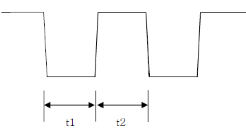
| Variable | Min | Typ | Max |
|---|---|---|---|
| t1 | 100 ms | - | 200 ms |
| t2 | 100 ms | - | 200 ms |
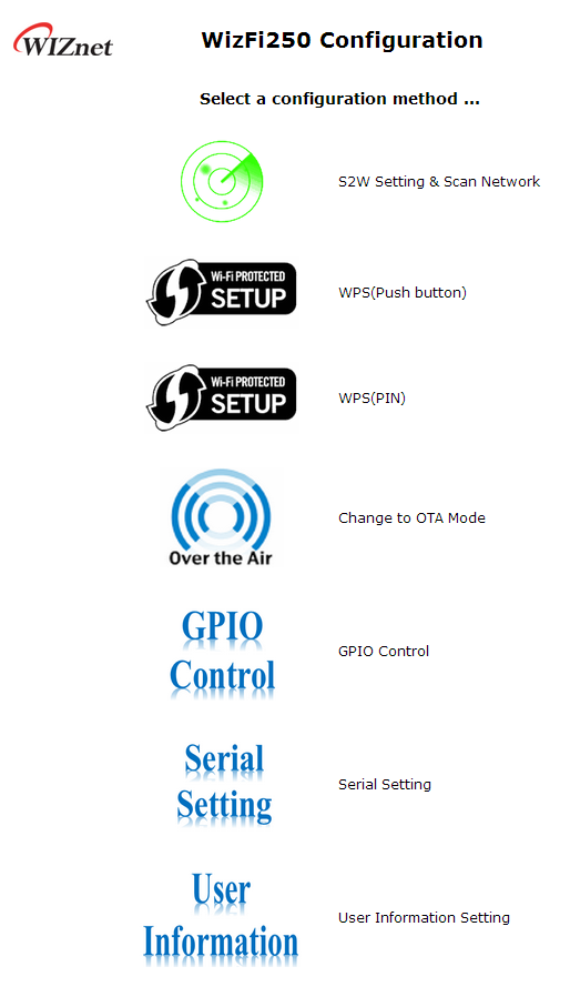
How to Use Web Configuration
Main Page
This picture shows the main page of WizFi250’s web server. In order to enter this page, WizFi250 should operate as SoftAP mode or associate to target AP as STA mode. The web server is launched automatically when joined to target AP or operate SoftAP. If you do not want to operate the web server, you can use <AT+FWEBS> command. For detailed information about <AT+FWEBS> command, refer to AT+FWEBS. After entering this page, users have to input user id and user password. Its default value is admin. If you want to change user id or user password, you can use <AT+MCWUI> command. For detailed information about <AT+MCWUI> command, refer to AT+MCWUI.

After input user information, user can choose an item to perform among below listed 5 items.
Serial to Wi-Fi Setting
If you select “S2W Setting & Scan Network” icon, you can enter into web page as shown in this picture. On this page, you can set parameters for using AP Mode or Station Mode and TCP/UDP.
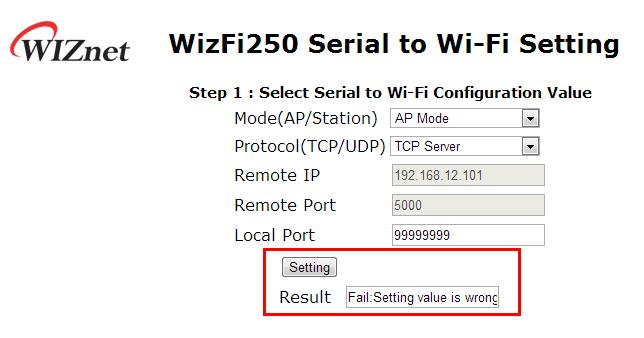
Set AP Mode
If you want to use AP Mode and TCP Server, you can select parameter as showm on picture. If you want to use TCP Server or UDP Server, you don't need to input <Remote IP> and <Remote Port>.
If WizFi250 was set successfully, you willsee the success message as below.
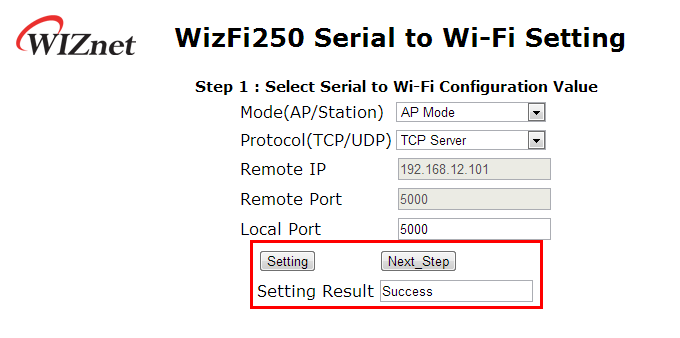
And after checking success result, click the <Next_Step> button in order to move on to the next page. If wrong value was inputted, WizFi250 will return fail message like below.
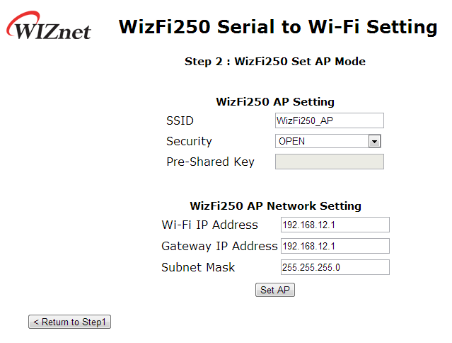
On the next page users can set AP information like SSID, Security and Security Key value as below.
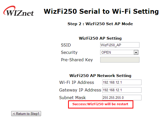
If it finishes successfully, the user will see the message as below.
Station Mode
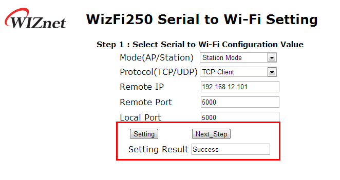
If the user seta Station Mode on this web page, the user can select protocol and other information as Remote IP, Remote Port and Local Port. In this example, we will explain how to set Station Mode and TCP Client.
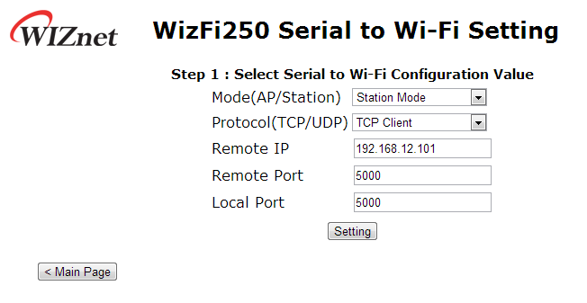
If WizFi250 was set successfully, you will see the success message as below.
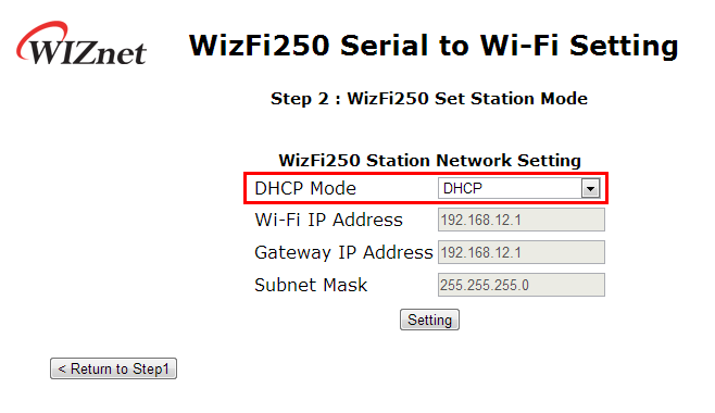
Then you can select DHCP mode or Static mode. In this example we chose DHCP mode. When using DHCP, it is not required to select IP information.
Enter a Password and then Select the <Join> button you want to associate to SSID.
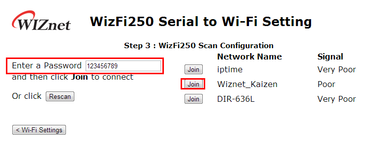
If you can see “Device Started. Web server and access point stopped. See UART for further information.” message in the web browser and “Successfully joined” message in the serial terminal, WizFi250 is associated to AP successfully. This picture is serial message when WizFi250 is associated to AP successfully.

WPS(Push Button)
This section explains how to set the protocol as TCP or UDP and then associate to Access Point by WPS method. If you select „WPS(Push button)“, you can see the web page as on this picture. For more detailed information, refer to Serial to Wi-Fi Setting.
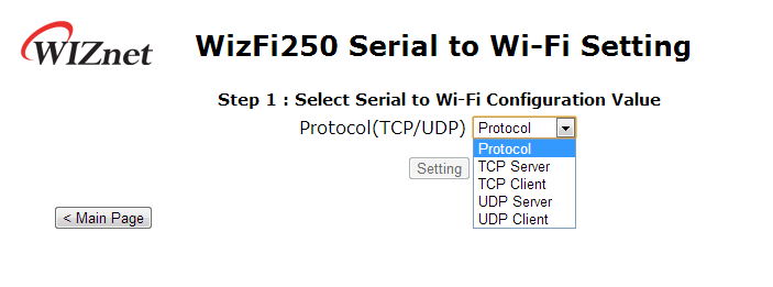
If you click the next_step button after finishing the setting, the web page will be shown as below.
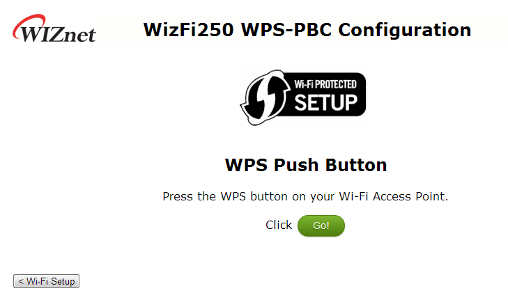
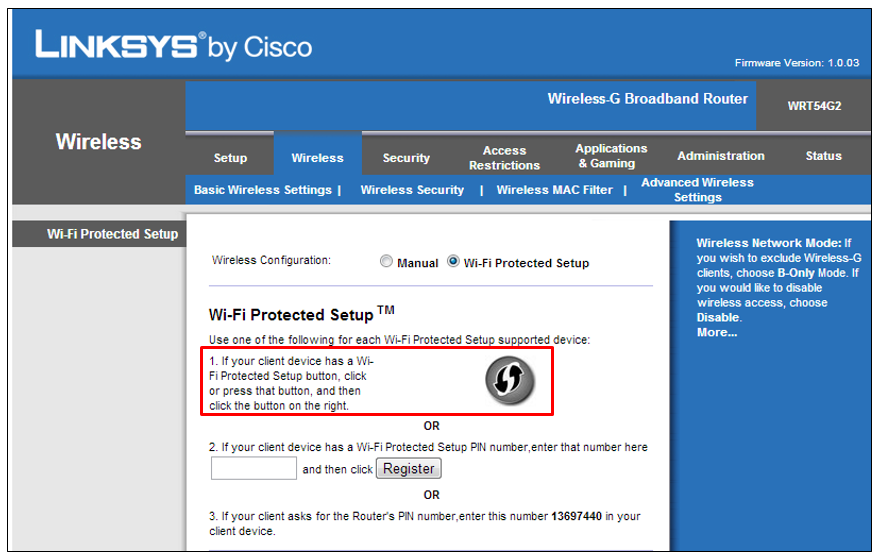
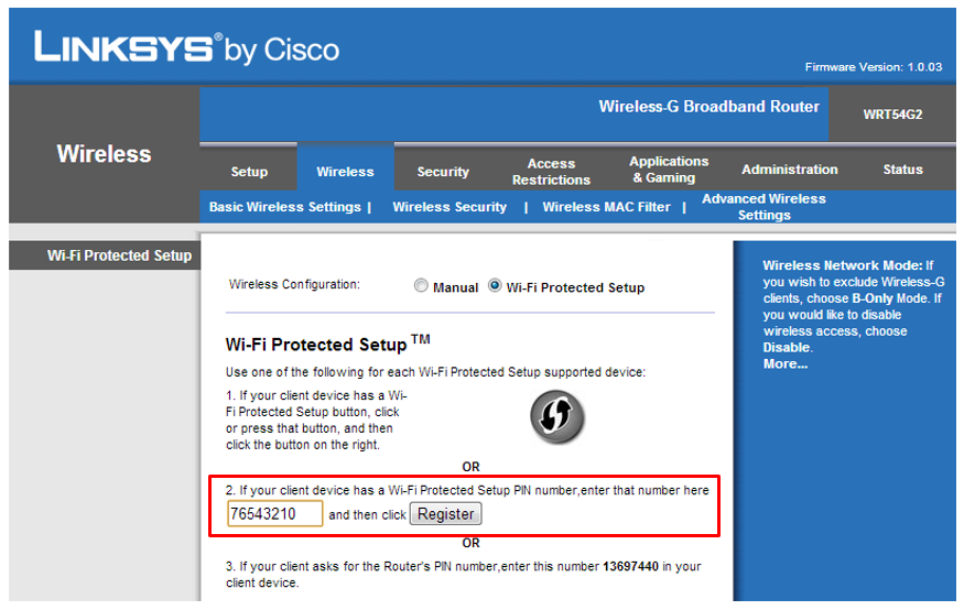
If you click the <Go> button on this web page, WizFi250 will scan the Access-Point in order to connect to it. The Access-Point must be set with <WPS-PBC> function as in this picture. ( In this example, we used LINKSYS Access-Point )
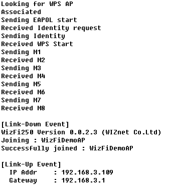
This picture shows the log message stating that WizFi250 finished the WPS function successfully.
WPS(PIN)
This section explains how to set the protocol as TCP or UDP and then associate it to the Access Point by WPS method. If you select “WPS(PIN)“, you will see the webpage as shown in this picture. For detailed information, refer to Serial to Wi-Fi Setting.
If you click the next_step button after finishing the setting, the web page will be shown as below.
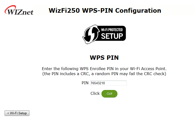
If you enter PIN number and click <Go> button, WizFi250 will scan the Access-Point in order to connect to it. Access-Point must be set as <WPS-PIN> function as below. ( In this example, we used LINKSYS Access-Point )
If the WPS-PIN function is successful, you will see a serial log message as on this picture.
Change to OTA Mode
If you select “Change to OTA Mode” icon, you will see the web page as on this picture.
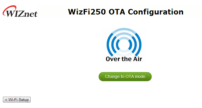
If you click the <Change to OTA mode> button on this page, WizFi250 will run in OTA Mode. For detailed information about OTA Mode, refer to Upload newest firmware in OTA mode
GPIO Control
If you select the “GPIO Control” icon you will see the web page as shown on this picture.
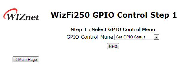
On this page, you can select “Get GPIO Status” menu or “Set GPIO Status” menu.
If you click “Next” button after selecting “Get GPIO Status” menu, you can see the web page as this picture.
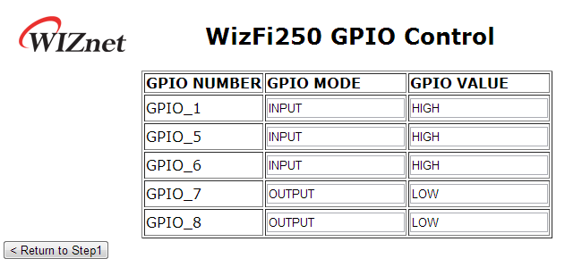
On this page, you can check the real time GPIO status of WizFi250.
If you select “Set GPIO Status” menu, you will see the web page as on this picture.
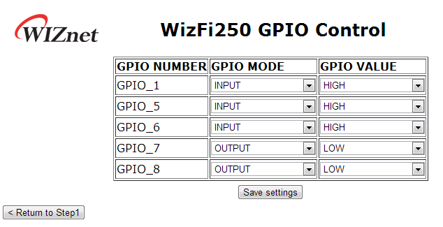
On this page, you can set gpio mode and gpio value of WizFi250.
- When set as output mode… mode, WizFi250 will set gpio config value to
OUTPUT_PUSH_PULL. - When set as input mode, WizFi250 will set gpio config value to INPUT_HIGH_IMPEDANCE.
For detailed information about it, refer to AT+FGPIO.
Serial Setting
If you select “Serial Setting” icon, you can see the web page as this picture.
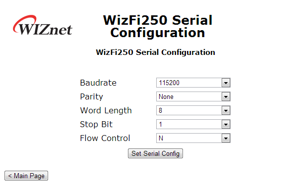
On this page, you can set serial information. When you select the <Set Serial Config> button after your choice values, WizFi250 will be restarted in order to change serial information. For detailed information about it, refer to AT+USET.
User Information Setting
If you select the „User Information“ icon, you will see the web page as in this picture.
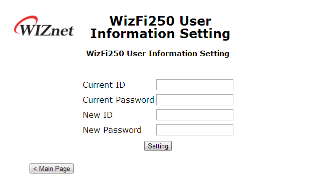
On this page, you can change user id and user password. For changing user information, you have to input current id and password.
If you select <Setting> button after input value, WizFi250 will be restarted in order to change user information. For detailed information about it, refer to AT+MCWUI.
How to Upgrade Firmware
Serial Line-APP+DCT
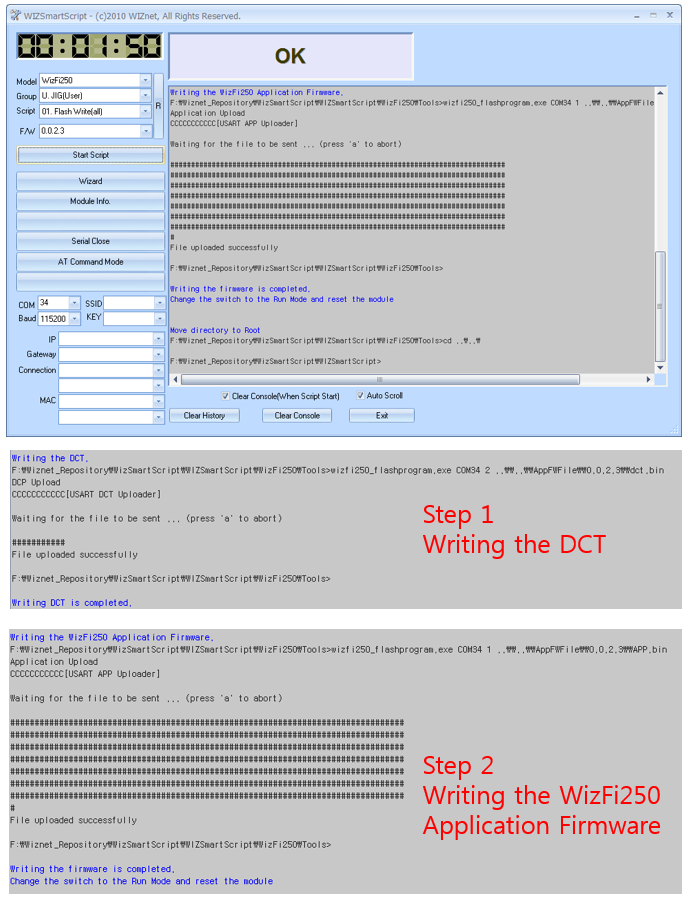
- Download WIZSmartScript from WIZnet homepage and install it
- Run WizFi250 in Boot Mode. (refer to boot pin in the PIN Description)
- Run WIZSmartScript and fill in options(RED) as below. (COM Port should match yours) And Click the 'Start Script' buton (Yellow).
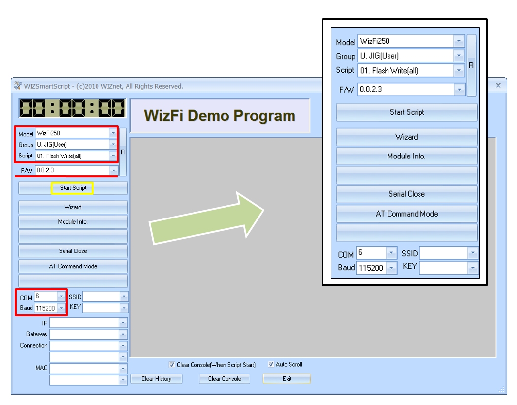
- Check the log that shows up as below. After 4 seconds, download will be started. First, write the DCT, then write the WizFi250 application firmware. If it is a success step1 message and step2 message. ( execute “02-A. Flash Write(app) if step2 fails ) ☞ If you want to change firmware binary file, just copy it to 'AppFWFile' folder.
Wi-Fi OTA(Over the Air) - APP
Start OTA mode using AT+FOTA Command
- Turn on OTA mode by entering the command as below.
AT+FOTA
[OK]
Start OTA mode using WEB Server
- Run WizFi250 in command mode, and operate the WizFi250 as below.
AT+WLEAVE
[OK]

AT+FWEBS=1,A
[OK]

AT+WSET=1,(SSID)
[OK]

AT+WSEC=1,(EncryptionType),(PreSharedKey)
[OK]

AT+WNET=0,192.168.0.2,255.255.255.0,192.168.0.2
[OK]

AT+WJOIN
[OK]

[Link-Up Event]
IP Addr    : 192.168.0.1
Gateway    : 192.168.0.1
[OK]
- Connect your PC Wi-Fi to the Wizfi250, open the web browser and enter the IP address of WizFi250 which you can find by using 'AT+WSTAT'
- Click the 'Over the Air' icon
- Click the 'Change to OTA mode' button, then WizFi250 will enter OTA mode.
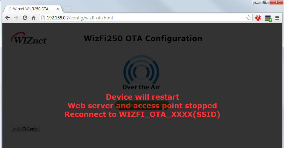
Start OTA mode using FUNCTION pin
- If entered the OTA Mode using FUNCTION pin, you will see messages as below. Refer to FUNCTION Pin Usage

Upload newest firmware in OTA mode
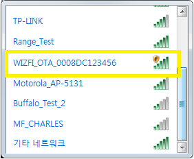
- Now you can connect to the WizFi250 OTA Access Point from your PC. Connect your PC WLAN to the AP which the name WIZFI_OTA_(MAC-Address).
-
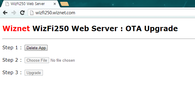
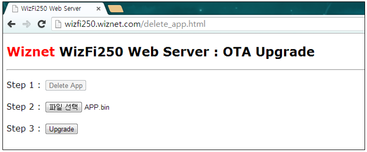
Open the WEB browser and go to 'wizfi250.wiznet.com'. (If the browser failed to find the page, disconnect the other network connections and try again). When successful, it should look like below.
-
Click the 'Delete App' button, and wait until internal flash memory is erased. (Before writing firmware, internal flash must be erased. Otherwise it does not work properly.).
-
After erase, click the second button, ‘Choose File’, and select the firmware file you want to upload.
-
Click the second button, 'Select file', and choose the FW file you want to upgrade. And finally, click the 'Upgrade' button to start upgrading. ( You have to use APP.bin file. This file is in WIZSmartScript\AppFWFile\Version\APP.bin )
-
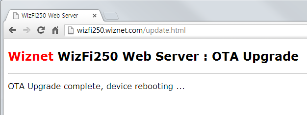
Wait for a second until upgrade is finished and check if it shows a complete message as below.
-
Check if WizFi250 is upgraded and works well.
Firmware Recovery
This section explains how to recover firmware when a critical problem occurred in WizFi250 application firmware.
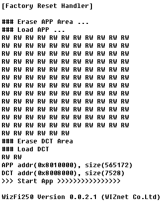
- Input low signal to BOOT pin and FUNCTION pin.
- Reboot WizFi250
- If WizFi250 starts the firmware procedure you will see a serial message as below. If this procedure succeeds, WizFi250 will be reset to factory default firmware.
- If you want to upload newest firmware to WizFi250, you have to use OTA mode. For detailed information for starting OTA mode, refer to Wi-Fi OTA.
- Afterwards, you can upload newest firmware using web browser. For detailed information for uploading newest firmware in web page, refer to Wi-Fi OTA - Upload newest firmware in OTA mode.
Examples - Association & Disassociation
Station Mode using WPA2 Static IP
This section explains how to connect to AP using WizFi250 with static IP address. In this example, target AP information is as below. ( SSID : WizFiDemoAP, Security : WPA2, Key : 12345678 )
AT   				(Sent AT command with 0x0d (Hex of Enter button))
[OK] 		 	 	(Response meaning successful execution)

AT+WSET=0,WizFiDemoAP	(AT command for setting WiFi association)
[OK]

AT+WSEC=0,WPA2,12345678	(AT command for setting WiFi security)
[OK]

AT+WNET=0,192.168.12.101,255.255.255.0,192.168.12.1	(AT command for setting Static IP address)
[OK]

AT+WJOIN			(AT command executing AP association)
Joining : WizFiDemoAP
Successfully joined : WizFiDemoAP

[Link-Up Event]
  IP Addr   : 192.168.12.101
  Gateway   : 192.168.12.1
[OK]

AT+WLEAVE			(AT command making disassociation from AP association)

[Link-Down Event]
[OK]
Station Mode using WPA2 DHCP
This section explains how to connect WizFi250 to target AP with DCHP Client Mode
AT   				(Sent AT command with 0x0d (Hex of Enter button))
[OK] 				(Response meaning successful execution)

AT+WSET=0,WizFiDemoAP	(AT command for setting WiFi association)
[OK]

AT+WSEC=0,WPA2,12345678	(AT command for setting WiFi security)
[OK]

AT+WNET=1	(AT command for setting DHCP)
[OK]

AT+WJOIN			(AT command executing AP association)
Joining : WizFiDemoAP
Successfully joined : WizFiDemoAP

[Link-Up Event]
  IP Addr   : 192.168.12.13
  Gateway   : 192.168.12.1
[OK]

AT+WLEAVE			(AT command making disassociation from AP association)

[Link-Down Event]
[OK]
AP Mode using WPA2 Static IP
This section explains how to set AP mode using WizFi250. In AP mode, WizFi250 have to set static IP address. (AT+WNET=0,xxx,xxx,xxx) After setting AP mode, WizFi250 will operate DHCP Server. Thus, when smart phone or other devices connect to WizFi250, WizFi250 will give IP address to connected device.
AT   				(Sent AT command with 0x0d (Hex of Enter button))
[OK] 				(Response meaning successful execution)

AT+WSET=1,WizFi250_AP	(AT command for setting WiFi association information)
[OK]

AT+WSEC=1,WPA2,12345678	(AT command for setting WiFi security)
[OK]

AT+WNET=0,192.168.12.105,255.255.255.0,192.168.12.1	(AT command for setting Static IP address)
[OK]

AT+WJOIN			(AT command executing run AP mode)
Joining : WizFi250_AP

[Link-Up Event]
  IP Addr   : 192.168.12.105
  Gateway   : 192.168.12.1
[OK]

AT+WLEAVE			(AT Command disassociating from AP association)

[Link-Down Event]
[OK]
Examples - Data Communication
Method of setting TCP Client and exchanging data in Data Mode
Socket Open
This section explains how to open < TCP Client Socket> and communicate with peer system. Below is an example showing how to set TCP Client and change the mode to data mode. It also explains parameters of < AT+SCON> command.
(AT+SCON=< OpenType>,< SocketType>,< RemoteIP>,< RemotePort>,< LocalPort>,< DataMode>)
If you enter < O> or < SO> value to < Open Type> parameter, WizFi250 will try to connect to TCP Server immediately.
But when using < S> value, WizFi250 will try to connect to TCP Server after reboot and you have to set SocketType,RemoteIP,RemotePort and LocalPort as below
In order to set WizFi250 to data mode, you have to enter 1 value to < Data Mode> parameter of AT+SCON command. For detailed information to this command, refer to AT+SCON.
- Mode: Data Mode, TCP Client
- Remote IP : 192.168.12.102
- Remote Port : 5000
- Local Port : 5001
AP Association                    ( Refers to Association & Disassociation Example )

AT+SCON=O,TCN,192.168.12.102,5000,5001,1 ( AT command connecting with a TCP Client Socket )
[OK]

[CONNECT 0]                          < = At this point, a TCP connection is done
Exchanging data with a peer system
If WizFi250 successfully connects to a peer system, WizFi250 will print [CONNECT(CID)] message and enter data mode. In data mode, WizFi250 can send serial data to peer system and receive network data from peer system without other translation.
Socket Close
In order to close TCP connection, WizFi250 has to switch to AT Command Mode. ( When +++ message entered, WizFi250 can be changed to AT Command Mode. ) After being changed to AT Command Mode, TCP Connection can be closed by using < AT+SMGMT=CID> or < AT+SMGMT=ALL> command.
Checking Socket Status
After being changed to AT Command Mode, TCP Connection can be closed by using < AT+SMGMT=CID> or < AT+SMGMT=ALL> command.
AT+SMGMT=?
Number of Sockets : 1 (SCID/Socket/Mode/Remote/Local/DataMode)
0/TCN/192.168.12.23:5000/5001/1
[OK]
Method of setting TCP Server and exchanging data in Data Mode
Socket Open
This section explains how to open < TCP Server Socket> and communicate with peer system. Below is the example for setting TCP Server and then changing to data mode. For detailed information about < AT+SCON> command, refer to AT+SCON and Socket Open.
- Mode : Data Mode, TCP Server
- Local Port : 5000
AP Association              ( Refer to Association & Disassociation Example )

AT+SCON=O,TSN, , ,5000,1        ( AT command listening with a TCP Server Socket )
[OK]

[CONNECT 0]          < = When TCP connection is done, you can see this message
Exchanging data with a peer system
Exchanging data with its peer system is the same as previous Exchanging data with a peer system.
Socket Close
Closing socket connection is the same as previous Socket Close.
Checking Socket Status
Checking socket status is the same as previous Checking Socket Status.
Method of setting UDP Client and exchanging data in Data Mode
Socket Open
This section explains how to open < UDP Client Socket> and communicate to peer system. Below is an example for setting up UDP Client and changing into data mode. For detailed information about < AT+SCON> command, refer to AT+SCON and Socket Open.
- Mode : Data Mode, UDP Client
- Remote IP : 192.168.12.23
- Remote Port : 5001
- Local Port : 5000
AP Association              ( Refer to Association & Disassociation Example )

AT+SCON=O,UCN,192.168.12.23,5001,5000,1
[OK]

[CONNECT 0]                          < = At this point, a UDP connection is done
Exchanging data with a peer system
Exchanging data with its peer system is the same as previous Exchanging data with a peer system.
Socket Close
Closing socket connection is the same as previous Socket Close.
Checking Socket Status
Checking socket status is the same as previous Checking Socket Status.
Method of setting UDP Server and exchanging data in Data Mode
Socket Open
This section explains how to open < UDP Server Socket> and communicate to peer system. Below is an example for setting up UDP Server and changing into data mode. For detailed information about < AT+SCON> command, refer to AT+SCON and Socket Open.
- Mode: Data Mode, UDP Server
- Local Port: 5000
AP Association ( Refer to Association & Disassociation Example )
AT+SCON=O,USN, , ,5000,1 [OK]
[CONNECT 0] < = At this point, a UDP connection is done
Exchanging data with a peer system
< UDP Server Mode> can connect UDP connection without peer systes information like IP address and port number. But before peer system is connected to WizFi250, WizFi250 does not send data to peer system because WizFi250 does not know its information. Thus peer system must send data to WizFi250 in order to know peer system’s information like below.
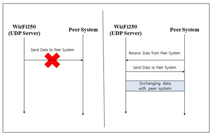 The other information for exchanging data is same as Exchanging data with a peer system.
Socket Close
Closing socket connection is the same as previous Socket Close.
Checking Socket Status
Checking socket status is the same as previous Checking Socket Status.
Method of setting TCP Client and exchanging data in Command Mode
Socket Open
This section explains how to set < TCP Client> in < Command Mode> and communicate to peer system. Below is the example for setting TCP Client on the Command Mode . In order to enter in the Command Mode, you have to enter 0 value to < Data Mode> parameter of < AT+SCON> command. For detailed information to this command, refer to AT+SCON
- Mode : Command Mode, TCP Client
- Remote IP: 192.168.12.23
- Remote Port : 5000
- Local Port : 5001
AP Association ( Refer to Association & Disassociation Example )
AT+SCON=O,TCN,192.168.12.23,5000,5001,0 [OK]
[CONNECT 0] < = At this point, a TCP connection is done
Exchanging data with a peer system
If WizFi250 connects to peer system successfully, WizFi250 will print [CONNECT(CID)] message. At this time, WizFi250 is in command mode. In order to send data to peer system, you have to use < AT+SSEND=CID, Destination IP, Destination Port, Data Length > command. If you input serial command like < Data Length > , WizFi250 will send serial data to peer system.
AT+SSEND=0,,,5 ( Sending data to a Socket with CID 0 ) Hello < = When serial data is 5byte, WizFi250 send this data to peer system [OK]
{ 0,192.168.12.23,5000,11 } Hi WizFi250 ( Receiving data from pear system )
Socket Close
In < AT Command Mode >, TCP connection can be closed through < AT+SMGMT=CID> or < AT+SMGMT=ALL> command.
Checking Socket Status
In < AT Command Mode >, Information of connected sockets are shown by using < AT+SMGMT=?> command.
AT+SMGMT=? Number of Sockets : 1 (SCID/Socket/Mode/Remote/Local/DataMode) 0/TCN/192.168.12.23:5000/5001/0 [OK]
Method of setting TCP Server and exchanging data in Command Mode
Socket Open
This section explains how to set < TCP Server> in < Command Mode> and communicate to peer system. Below is the example for setting TCP Server on the Command Mode. For detailed information about < AT+SCON> command, refer to AT+SCON and Socket Open.
-
Mode : Command Mode, TCP Server
-
Local Port : 5000
AP Association ( Refer to Association & Disassociation Example )
AT+SCON=O,TSN, , ,5000,0 ( AT command listening with a TCP Server Socket ) [OK]
[CONNECT 0]
Exchanging data with a peer system
Exchanging data with its peer system is the same with previous Exchanging data with a peer system.
Socket Close
Closing socket connection is the same with previous Socket Close.
Method of setting UDP Client and exchanging data in Command Mode
Socket Open
This section explains how to set < UDP Client> in < Command Mode> and communicate to peer system. Below is an example for setting UDP Client on Command Mode. For detailed information about < AT+SCON> command, refer to AT+SCON and Socket Open.
-
Mode : Command Mode, UDP Client
-
Remote IP : 192.168.12.23
-
Remote Port : 5001
-
Local Port : 5000
AP Association ( Refer to Association & Disassociation Example )
AT+SCON=O,UCN,192.168.12.23,5001,5000,0 [OK]
[CONNECT 0] < = At this point, a UDP connection is done
Exchanging data with a peer system
Exchanging data with its peer system is the same as previous Exchanging data with a peer system.
Socket Close
Closing socket connection is the same as previous Socket Close.
Method of setting UDP Server and exchanging data in Command Mode
Socket Open
This section explains how to open < UDP Server Socket> in Command Mode and communicate to peer system. Below is an example for setting UDP Server on Command Mode. For detailed information about < AT+SCON> command, refer to AT+SCON and Socket Open.
-
Mode : Command Mode, UDP Server
-
Local Port : 5000
AP Association ( Refer to Association & Disassociation Example )
AT+SCON=O,USN, , ,5000,0 [OK]
[CONNECT 0]
Exchanging data with a peer system
< UDP Server Mode> of WizFi250 can connect UDP connection without peer system information like IP address and port number. Before peer system is connected to WizFi250, WizFi250 does not send data to peer system. So you should be careful when using < UDP Server Mode>.
{0,192.168.12.23,5001,11} Hi WizFi250 ( Receiving data from peer system )
AT+SSEND=0,,,5 ( Sending data to a Socket with CID 0 ) Hello < = When serial data is 5byte, WizFi250 send this data to peer system [OK ]
AT+SCON
AT+SCON=< OpenType>,< SocketType>,< RemoteIP>,< RemotePort>,< LocalPort>,< DataMode>
This section explains the usage of < Open Type> parameter of < AT+SCON> command. This table describes values of < Open Type> parameter.
Parameter Meaning S Register as a Service O Open at Once SO Open at Once & Register as a Service < S> : Register as a Service When using this parameter, WizFi250 will try to connect to peer system using TCP or UDP when power is on.
AT+WLEAVE [OK]
AT+WSET=0,WizFiDemoAP [OK]
AT+WSEC=0,WPA2,12345678 [OK]
AT+WNET=1 [OK]
AT+SCON=S,TSN,,,5000,0 [OK]
AT+MPROF=S [OK]
AT+MRESET [OK] WizFi250 Version 0.9.0.0 (WIZnet Co.Ltd) Joining : WizFiDemoAP Successfully joined : WizFiDemoAP
[Link-Up Event] IP Addr : 192.168.12.10 Gateway : 192.168.12.1
AT+SMGMT=? Number of Sockets : 1 (SCID/Mode/Remote/Local/DataMode) 0/TSN/0.0.0.0:0/5000/0 [OK]
< O> : Open at Once When using this parameter, WizFi250 will try to connect to peer system using TCP or UDP when enter the < AT+SCON> command. For using this parameter, WizFi250 should be already associated with AP or running AP mode. In this section, we have only explained steps in Station Mode. In AP Mode, you can use this command like in Station Mode
AT+WLEAVE [OK]
AT+WSET=0,WizFiDemoAP [OK]
AT+WSEC=0,WPA2,12345678 [OK]
AT+WNET=1 [OK]
AT+WJOIN Joining : WizFiDemoAP Successfully joined : WizFiDemoAP
[Link-Up Event] IP Addr : 192.168.12.10 Gateway : 192.168.12.1 [OK]
AT+SCON=O,TCN,192.168.12.23,5000,,0 [OK]
[CONNECT 0] < SO> Open at Once & Register as a Service When using this parameter, you can use functions of < S> and < O> at the same time. When using this parameter, WizFi250 will try to connect to peer system momentarily. And if you restart WizFi250, WizFi250 will try to connect to AP and peer system.
AT+WLEAVE [OK]
AT+WSET=0,WizFiDemoAP [OK]
AT+WSEC=0,WPA2,12345678 [OK]
AT+WNET=1 [OK]
AT+WJOIN Joining : WizFiDemoAP Successfully joined : WizFiDemoAP
[Link-Up Event] IP Addr : 192.168.12.10 Gateway : 192.168.12.1 [OK]
AT+SCON=SO,TCN,192.168.12.23,5000,,0 [OK] [CONNECT 0]
AT+MPROF=S [OK]
AT+MRESET [OK]
WizFi250 Version 0.9.0.0 (WIZnet Co.Ltd) Joining : WizFiDemoAP Successfully joined : WizFiDemoAP
[Link-Up Event] IP Addr : 192.168.12.10 Gateway : 192.168.12.1
[CONNECT 0]
Example of SSL Connection
This section explains how to connect to and communicate with SSL server. To connect to SSL server, use < TCS(TCP Client SSL)> / < TSS(TCP Server SSL)> parameter of < AT+SCON> command. ( When using UDP, WizFi250 cannot use SSL Connection. ) In order to use SSL connection, you can use AT command as below.
AT+SCON=SO,TCS,199.59.148.212,443,5000,0
[OK]
[CONNECT 0]
AT+SSEND=0,,,18
GET / HTTP/1.1{0x0d}{0x0a}
{0x0d}{0x0a}
[OK]

{0,173.194.33.38,443,990}HTTP/1.1 302 Found
Location: https://www.google.co.kr/
Cache-Control: private
Content-Type: text/html; charset=UTF-8
Set-Cookie: PREF=ID=3e64d81fb97c7e6c:FF=0:TM=1371553236:LM=1371553236:S=H3NKySD63UwelF_z; expires=Thu, 18-Jun-2015 11:00:36 GMT; path=/; domain=.google.com
Set-Cookie: NID=67=vtzYXz5msxRYzO-KzH5EKgcnABE4_YOcbUG1RGXufiQM2PNc84gyr8O12VNkOOap8MUCmGNQfnfsGMarSS9Jlkb7MiZdIQxrJg-FL1uKUqgSBA2CGIEqI5syrKnNW2YK; expires=Wed, 18-Dec-2013 11:00:36 GMT; path=/; domain=.google.com; HttpOnly
P3P: CP="This is not a P3P policy! See http://www.google.com/support/accounts/bin/answer.py?hl=en&answer=151657 for more info."
Date: Tue, 18 Jun 2013 11:00:36 GMT
Server: gws
Content-Length: 222
X-XSS-Protection: 1; mode=block
X-Frame-Options: SAMEORIGIN

<HTML><HEAD><meta http-equiv="content-type" content="text/html;charset=utf-8"><TITLE>302 Moved</TITLE></HEAD><BODY><H1>302 Moved</H1>The document has moved< A HREF="https://www.google.co.kr/">here</A>.
</BODY></HTML>
[DISCONNECT 0]
Example of Multi Socket Connection
This section explains how to use < Multi Socket Connection> function. WizFi250 can use max 8 TCP or UDP sockets. In order to use < Multi Socket Connection> function, you can use AT command as below. In this example, the peer system was running a loop back program. So if peer system received data from WizFi250, peer system will send received data to WizFi250.
AP Association
AT+SCON=O,TCN,192.168.12.23,5000,5001,0 [OK]
[CONNECT 0] AT+SCON=O,TSN,,,6000,0 [OK]
[CONNECT 1] AT+SCON=O,UCN,192.168.12.23,7000,7000,0 [OK]
[CONNECT 2] AT+SCON=O,USN,,,8000,0 [OK]
[CONNECT 3] AT+SMGMT=? Number of Sockets : 4 (SCID/Socket/Mode/Remote/Local/DataMode) 0/TCN/192.168.12.23:5000/5001/0 1/TSN/192.168.12.23:58769/6000/0 2/UCN/192.168.12.23:7000/7000/0 3/USN/0.0.0.0:/8000/0 [OK]
AT+SSEND=0,,,16 Hello_TCP_Client [OK]
{0,192.168.12.23,5000,16}Hello_TCP_Client
AT+SSEND=1,,,16 Hello_TCP_Server [OK]
{1,192.168.12.23,58769,16}Hello_TCP_Server
AT+SSEND=2,,,16 Hello_UDP_Client [OK]
{2,192.168.12.23,7000,16}Hello_UDP_Client {3,192.168.12.23,8000,16}Hello_UDP_Server AT+SSEND=3,,,16 Hello_UDP_Server [OK]
Air Command mode - WizFi250AirCmd
This section explains how to operate Air-command-mode of WizFi250. With this Air-command-mode included in the WizFi250, you can issue AT commands to the module via WiFi, while the WizFi250 is in the TCP server or UDP server operation mode.
Please have a look at the following hints:
- Air-command-mode should only be used for configuration of WizFi250. It is not recommended to use the command mode for other purpopses.
- The Air-command-mode will automatically be started, when the module WizFi250 will be booted into the AP mode. The module can then be configured on the port 50001 on its IP address.
The AT command consists of following parts: Command header (WizFi250AirCmd:), AT command (for example: AT) and Carriage Return (\r).
The command should be sent with these conditions:
- The command header “WizFi250AirCmd:” is case sensitive and has to be sent in this kind. It is 15 Bytes long.
- A < Carriage Return, 0x1d> has to follow the AT command directly.
- Air-command header, AT command and Carriage Return should be combined into one packet.
Example usage of the WizFi250AirCmd:
AT+WSET=1,WizFi250_AIRCMD [OK] AT+WSEC=1,WPA2,123456789 [OK] AT+WNET=0,192.168.11.1,255.255.255.0,192.168.11.1 [OK] AT+WJOIN
[Link-Up Event] IP Addr : 192.168.11.1 Gateway : 192.168.11.1 [OK]
AT+MAIRCMD=O,T,50001,0 [OK]
Now, TCP Client can connect to the WizFi250 and issue the AT commands via WiFi as below.
(TCP Client TX) WizFi250AirCmd:AT+MINFO\r (24 Byte) (RX) FW version/HW version 1.0.1.8/WizFi250 Rev 1.0 [OK]
(TCP Client TX) WizFi250AirCmd:AT+WSEC=?\r (25 Byte) (RX) 1,WPA2,123456789 [OK]
(TCP Client TX) WizFi250AirCmd:AT+WSEC=1,WPA2,aaaabbbb\r (39 Byte) (RX) [OK]
(TCP Client TX) WizFi250AirCmd:AT+MMAC=?\r (25 Byte) (RX) 00:08:DC:00:55:76 [OK]
Examples - WiFi Direct
This section explains how to connect to smartphone using WizFi250 with
< WiFi Direct>. In this example, target smartphone information is as
below.
( smartphone model : Samsung Galaxy Note 2, Android Version : 4.3, Model
Number : SHV-E250S )
Basic Information
< WiFi Direct> is supported after WizFi250 F/W v1.0.1.1.
WizFi250 Version 1.0.1.1 (WIZnet Co.Ltd)
at+minfo
FW version/HW version
1.0.1.1/WizFi250 Rev 1.0
[OK]
WiFi Direct Start
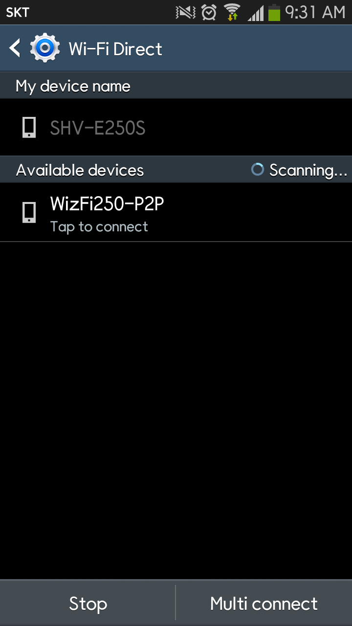
First, you need to enable < WiFi Direct> in your smartphone.
And, you can start < WiFi Direct> in WizFi250 using < AT+WP2P_START>
command.
AT+WP2P_START
STA MAC: CE:52:AF:C6:CF:B5
[OK]
WiFi Direct Connect
To connect your smartphone to WizFi250 via < WiFi Direct>, select
< WizFi250-P2P> in the list as below.
After a few seconds, your smartphone will connect to WizFi250 via
< WiFi Direct >
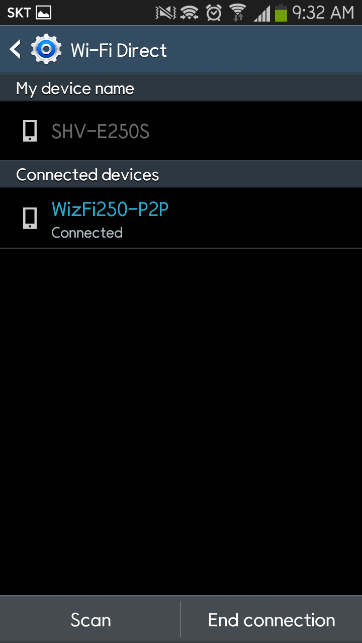
And you can see the result of < WiFi Direct> in WizFi250.
AT+WP2P_START STA MAC: CE:52:AF:C6:CF:B5 [OK] Found P2P device: SHV-E250S Sending Identity Sending Identity Sending nonce Sending hashes Sending WSC Done
[Link-Up Event] IP Addr : 192.168.49.219 Gateway : 192.168.49.1
As above, ip address of WizFi250 is < 192.168.49.219 > and that of smartphone is < 192.168.49.1 >
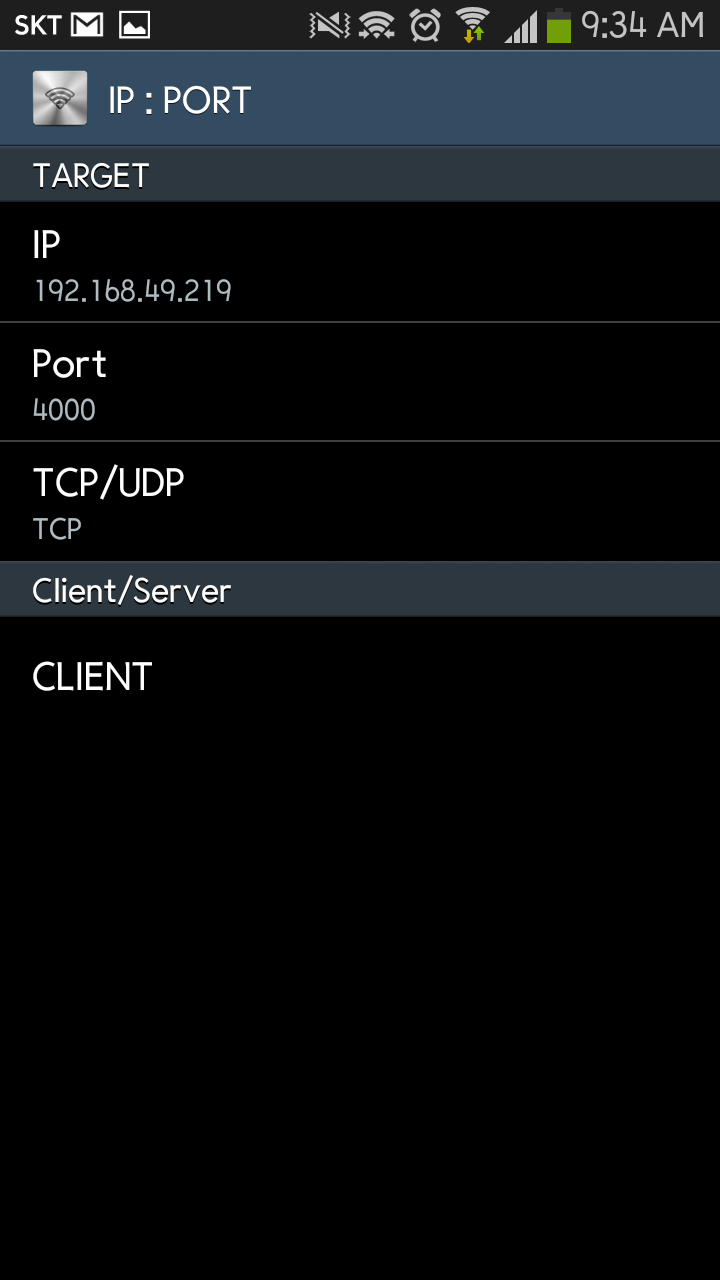
Data Communication
After the connection, you can issue < AT+SCON > command for for data communication.
at+scon=o,tsn,,,4000,0
[OK]
And, I just used a general TCP client App in the smartphone for the
test.
Now, WizFi250 and smartphone can communicate each other via < WiFi Direct>.
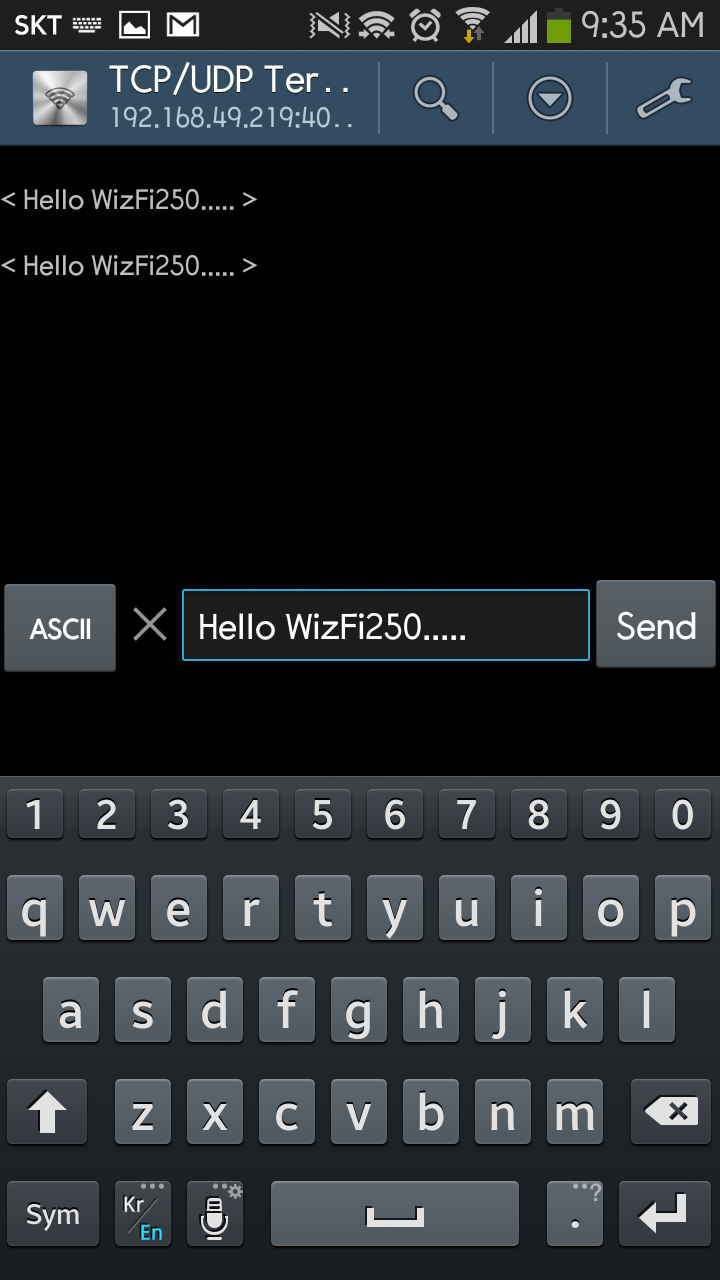
at+scon=o,tsn,,,4000,0
[OK]

[CONNECT 0]

{0,192.168.49.1,47160,19}Hello WizFi250.....
{0,192.168.49.1,47160,19}Hello WizFi250.....`
Appendix
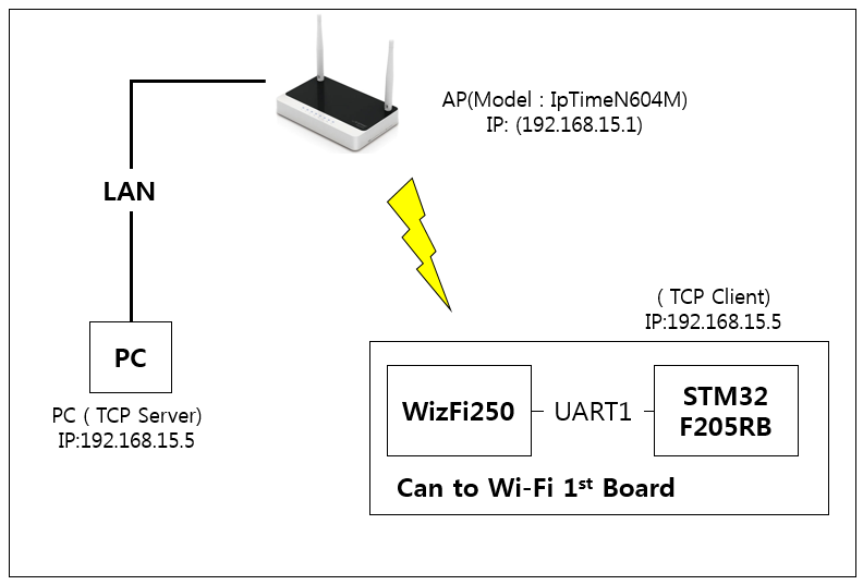
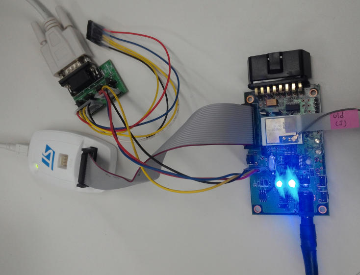
WizFi250 UART Throughput Test Report
Test Environment
Test Result
- Send 10Mbyte data to PC
| Baud rate | Time (Using Command Mode) | Speed(bit/s) | Flow Control |
|---|---|---|---|
| 3686400 | 47s | 1.74M | H/W |
| 1843200 | 1m 20s | 1.00M | H/W |
| 921600 | 2m 20s | 585K | H/W |
- Send 1Mbyte data to PC
| Baud rate | Data Mode | Command Mode | Flow Control | ||
|---|---|---|---|---|---|
| ::: | Time | Speed(bit/s) | Time | Speed(bit/s) | ::: |
| 3686400 | 24s | 341K | 5s | 1.63M | H/W |
| 1843200 | 25s | 327K | 6s | 1.36M | H/W |
| 921600 | 26s | 315K | 12s | 682K | H/W |
| 115200 | 1m 35s | 86K | 1m 36s | 85K | H/W |
- Command Mode : To sending data, WizFi250 have to use AT+SSEND command.
- Data Mode : Data Mode is the mode which passes data of application layers to peer-device directly, without commands.
- For more information, Refer to Command mode & Data mode.