Datasheet-KO
WIZ550SR Datasheet
개요
본 페이지는 WIZ550SR과 WIZ550-EVB 보드들에 대한 하드웨어 관련 정보를 제공하기 위한 것으로
- 기본적인 하드웨어 스펙
- AC/DC 특성
- 레퍼런스 회로도
- 모듈의 Dimension 정보
가 포함된다.
향후 하드웨어 사양이나 외형에 변경이 있을 경우에는 변경한 내역이 추가될 수 있다.
Hardware Specification
WIZ550SR
- 아주 작은 사이즈의 Serial to Ethernet Module.
- WIZnet의 TCP/IP Chip인 W5500 기반의 Serial to Ethernet Module.
- STmicro의 STM32F103RCT6 기반의 Serial to Ethernet Module.
- 2.00mm Pitch Pin Header 1x11 2ea 지원.
- MDI(Medium Dependent Interface) 지원.
- TXN, TXP, RXN, RXP
- UART Interface 지원.
- RXD, TXD, RTS, CTS, DSR(Option), DTR(Option)
- RS-232C Interface 지원 가능.
- RS-422/485 Interface 지원 예정.
- Debug UART 지원.
- DEBUG RXD, DEBUG TXD
- PHY Status Output 지원.
- Active LED, Link LED
- STATUS Output 지원.
- LOW : TCP Connect 상태.
- HIGH : TCP Diconnect 상태.
- 시스템 ��핀.
- RESET : 시스템 리셋, Active Low.
- BOOT0 : MCU BOOT 모드 진입, Active High.
- H/W TRIG : App BOOT 모드 진입, Active Low.
- Indicator LED 지원.
- Power LED(LD3).
- LED 0(LD1) :
- LED 1(LD2) :
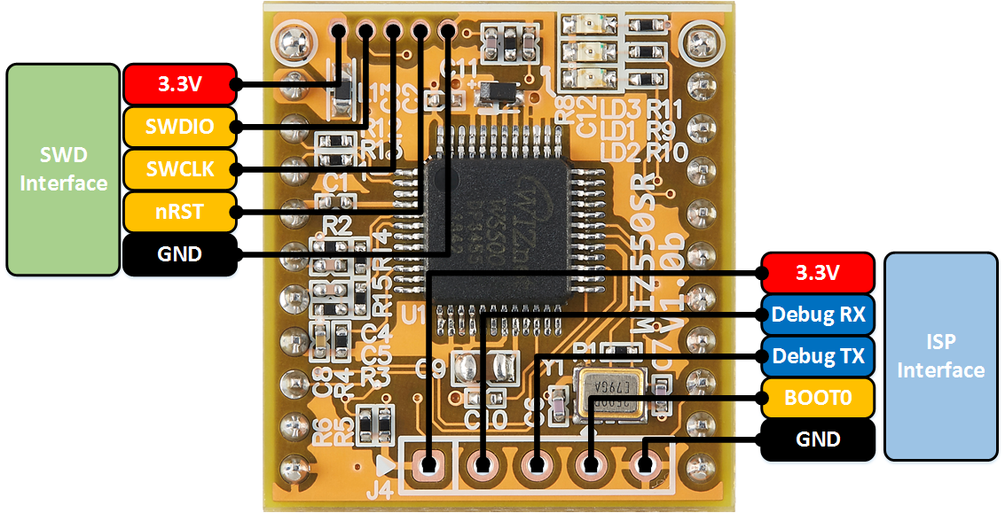
- Firmware 업로드용 Pin Header Hole 지원.
- 2.54mm Pitch, Not Mount.
- SWD 용 Pin Header Hole 지원.
- 1.27mm Pitch, Not Mount.
- Data 저장용 EEPROM 내장.
- Operation Temperature : -40℃ ~ 85℃
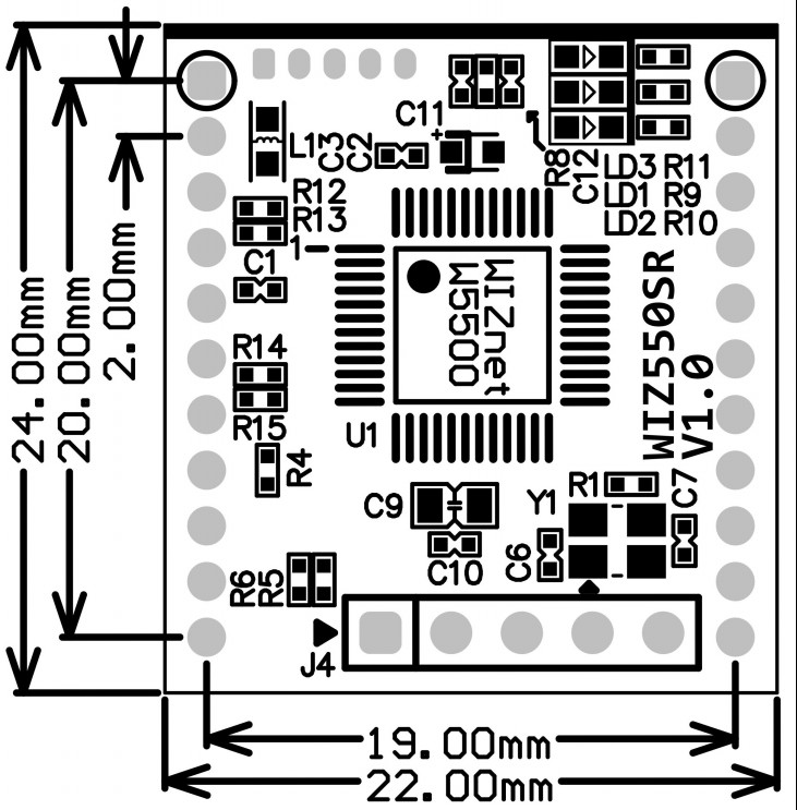
- Size : 22mm x 24mm x 13mm
WIZ550SR Pin Out
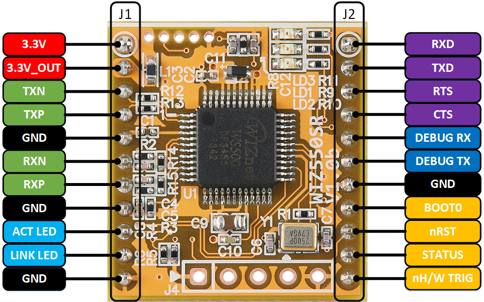
WIZ550SR Pin Description
| Ref No. | Pin No. | Symbol | Type | Description |
|---|---|---|---|---|
| J1 | 1 | 3.3V | P | +3.3V Input Power |
| ::: | 2 | 3.3V_OUT | P | +3.3V Output Power. This pin is connected to the TX resistor of MDI signal and Center TAP of RJ45. |
| ::: | 3 | TXN | O | MDI Signal. TX Negative. |
| ::: | 4 | TXP | O | MDI Signal. TX Positive. |
| ::: | 5 | GND | P | Ground. |
| ::: | 6 | RXN | I | MDI Signal. RX Negative. |
| ::: | 7 | RXP | I | MDI Signal. RX Positive. |
| ::: | 8 | GND | P | Ground. |
| ::: | 9 | ACT LED | O | PHY Active LED |
| ::: | 10 | LINK LED | O | PHY Link LED |
| ::: | 11 | GND | P | Ground. |
| Ref No. | Pin No. | Symbol | Type | Description |
|---|---|---|---|---|
| J2 | 1 | RXD | I | Data UART. Recieve Pin. |
| ::: | 2 | TXD | O | Data UART. Transmit Pin. |
| ::: | 3 | RTS | O | Data UART. Request to Send Pin. |
| ::: | 4 | CTS | I | Data UART. Clear to Send Pin. |
| ::: | 5 | DEBUG_RX | I | Debug UART. Recieve Pin. |
| ::: | 6 | DEBUG_TX | O | Debug UART. Transmit Pin. |
| ::: | 7 | GND | P | Ground. |
| ::: | 8 | BOOT0 | I | MCU Boot. Active High |
| ::: | 9 | nRST | I | Reset. Active Low |
| ::: | 10 | STATUS | O | Status Output. High : TCP Disconnect. Low : TCP Connect. |
| ::: | 11 | nH/W TRIG | I | App Boot. Hardware TRIG Input. Active Low |
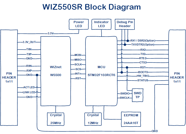
WIZ550SR Block Diagram
WIZ550SR EVB
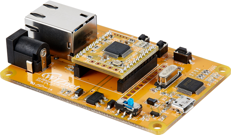
- WIZ550SR Developer Board.
- USB to UART chip, FT2232D.
- RJ45 with Transformer, RB1-1D5B8K1A.
- RESET Tact SW.
- BOOT0 Tact SW.
- H/W Trig Tact SW.
- LED Indicators.
- Micro USB.
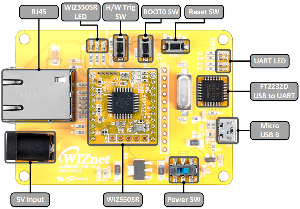
WIZ550SR EVB Call Out
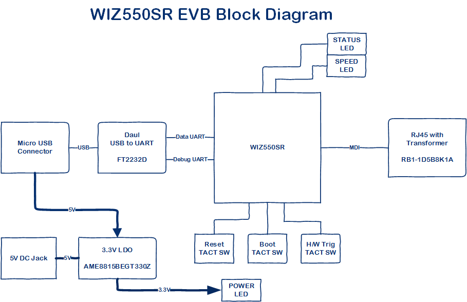
WIZ550SR EVB Block Diagram
Electrical Characteristics
Operating conditions at power-up / power-down
| Symbol | Parameter | Conditions | Min | Max | Unit |
|---|---|---|---|---|---|
| TVDD | VDD rise time rate | - | 0 | - | us/V |
| ::: | VDD fall time rate | ::: | 20 | - | ::: |
DC Characteristics
| Symbol | Parameter | Pins | Min | Typ | Max | Unit |
|---|---|---|---|---|---|---|
| VDD | Supply voltage | 3.3V | 2.97 | 3.3 | 3.6 | V |
| VIL | High level input voltage | ALL | 1.833 | 3.6 | V | |
| VIH | Low level input voltage | ALL | -0.3 | 1.166 | V | |
| VOL | Low level output voltage | ALL | 0.4 | V | ||
| VOH | High level output voltage | ALL | 3.0 | V | ||
| LOL | Low level input Current Sink Current | ALL | -25 | mA | ||
| LOH | High level output Current Source Current | ALL | 25 | mA | ||
| IDD | Supply Current (Normal operation mode) | 3.3V | TBD | mA |
nRST pin Characterisrics
| Symbol | Parameter | Conditions | Min | Typ | Max | Unit |
|---|---|---|---|---|---|---|
| VIL(nRST) | NRST Input low level voltage | - | -0.5 | - | 0.8 | V |
| VIH(nRST) | NRST Input high level voltage | - | -2 | - | 3.8V | V |
| Vhys(nRST) | NRST Schmitt trigger voltage hysteresis | - | - | 200 | - | mV |
| RPU | Weak pull-up equivalent resistor | - | 30 | 40 | 50 | kΩ |
| VF(nRST) | NRST Input filtered pulse | - | - | - | 100 | ns |
| VNF(nRST) | NRST Input not filtered pulse | - | 300 | - | - | ns |
Power Dissipation
| Condition | Min | Typ | Max | Unit |
|---|---|---|---|---|
| 100M Link | - | TBD | - | mA |
| 10M Link | - | TBD | - | mA |
| Un-Link (Auto-negotiation mode) | - | TBD | - | mA |
| 100M Transmitting | - | TBD | - | mA |
| 10M Transmitting | - | TBD | - | mA |
| Power Down mode | - | TBD | - | mA |
Schematics & BOM
Ref. Schematic
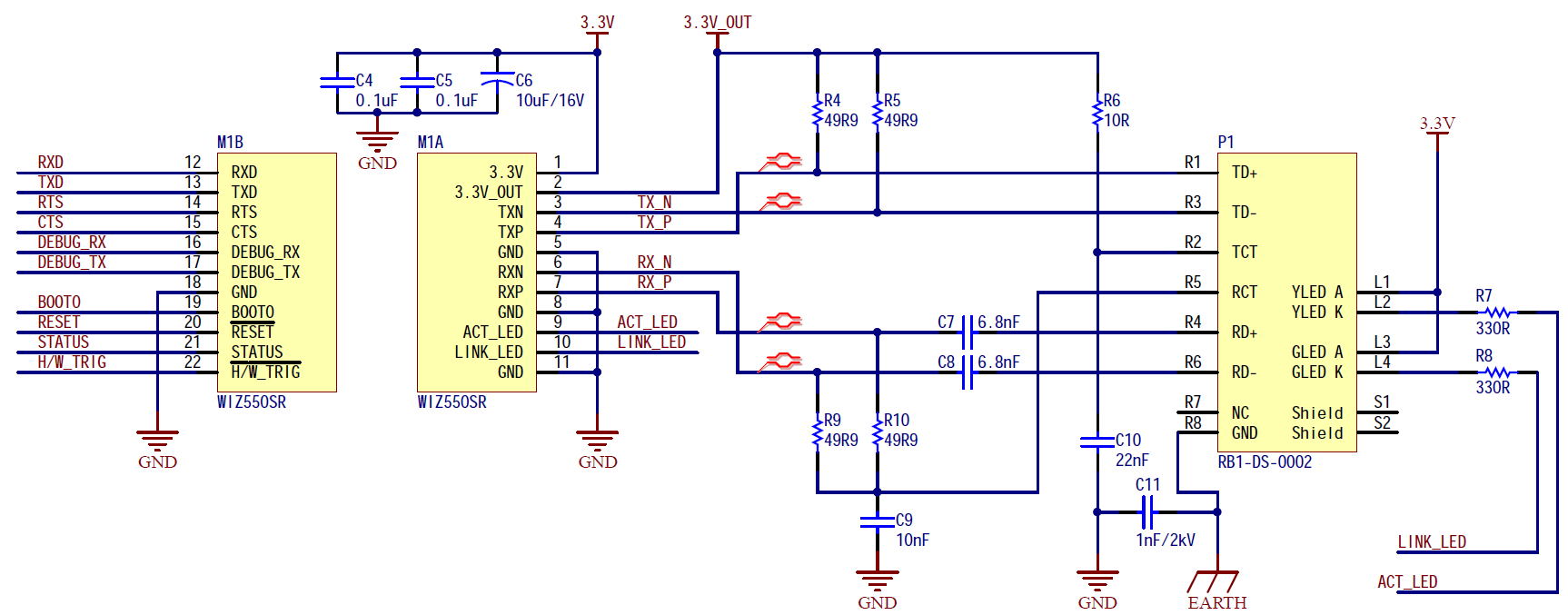
- WIZ550SR Ref Schematic : Download
WIZ550SR Schematic
-
WIZ550SR V1.0 Schematic : Download(Altium)
- WIZ550SR V1.0 Schematic : Download(PDF)
WIZ550SR BOM
- WIZ550SR V1.0 BOM: Download
WIZ550SR EVB Schematic
- WIZ550SR EVB V1.0 Schematic : Download(Altium)
* WIZ550SR EVB V1.0 Schematic : Download(PDF)
WIZ550SR EVB BOM
- WIZ550SR EVB V1.0 BOM : Download
Dimension
- WIZ550SR V1.0 3D PDF : Download
- This PDF must be run using the 'Adobe Acrobat'.