
WIZ-IP20
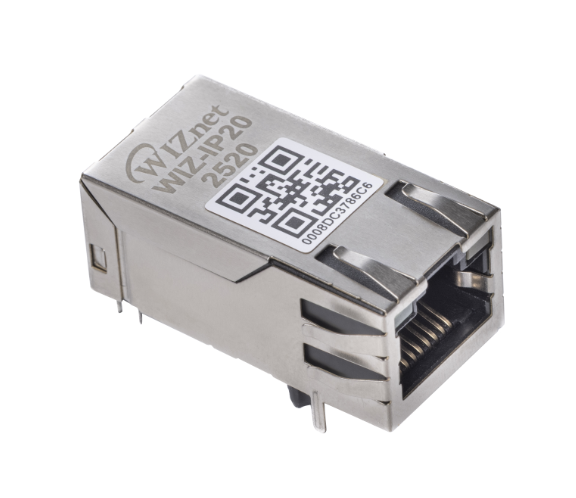
WIZ-IP20
WIZ-IP20 is a Serial to Ethernet converter in Mag Jack based on WIZnet's W55RP20 MCU.
WIZnet S2E Solution
-
WIZnet 'Serial to Ethernet' product is a protocol converter that transmits data sent by serial equipment as TCP/IP data and converts the TCP/IP data received through the network back into serial data to the serial equipment.
-
With this product, it is possible to easily add an Ethernet networking function to a device supporting UART/SPI interface, the devices can be controlled via an Ethernet network - Internet.
-
We also provide Customization Services such as change / add functions by customer request.
Features
The following key features are included with the WIZ-IP20 product.
- 10/100Mbps Ethernet & Up to 921,600bps serial speed
- Easy to add Ethernet networking function through UART or SPI interface of any device / MCU
- Support RS-232C and RS-422/485 if an external circuit is configured.
- Status pins: PHY link status / TCP connection status / Run status
- Support multiple protocols
- TCP Server
- TCP Client
- SSL TCP Client
- TCP Mixed
- Modbus RTU/ASCII (available only in TCP Server mode)
- UDP (multicast supported)
- MQTT Client
- MQTTS Client
- Support custom protocols (Please submit custom protocol requests via this link.)
- HTTP
- HTTPS
- CoAP
- External device OTA
- Support serial data packing
- Support TCP connection password
- Configuration is possible via serial AT commands or via Configuration tool
- Separate Data UART and Debug UART port
- Unique MAC Address (WIZnet OUI)
Hardware Design Guide & References
Pin Assignment
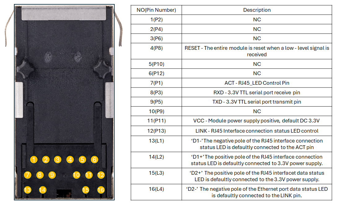
Top View
| Pin Number | Pin Name | Pin Type | Description |
|---|---|---|---|
| P1 | ACT | RJ45_LED Control Pin | RJ45 Interface data status LED control |
| P2 | USB_P | USB port | USB pins for firmware upload |
| P3 | RXD | Serial Port | 3.3V TTL serial port receive pin. |
| P4 | USB_N | USB port | USB pins for firmware upload |
| P5 | TXD | Serial Port | 3.3V TTL serial port transmit pin. |
| P6 | CTS | Serial Port | 3.3V TTL serial port CTS pin |
| P8 | RESET | Reset Pin | The entire module is reset when a low-level signal is received. |
| P9 | GND | Power Ground | Module power ground |
| P10 | RTS | Serial Port | 3.3V TTL serial port RTS pin |
| P11 | VCC | Positive Power Supply Pin | Module power supply positive, default DC 3.3V |
| P12 | BOOT | BOOT | BOOT pin for enter BOOT |
| P13 | LINK | RJ45_LED Control Pin | RJ45 Interface connection status LED control. |
| L1 | D1- | RJ45_LED | The negative pole of the RJ45 interface connection status LED is defaultly connected to the ACT pin |
| L2 | D1+ | RJ45_LED | The positive pole of the RJ45 interface connection status LED is defaultly connected to 3.3V power supply. |
| L3 | D2+ | RJ45_LED | The positive pole of the RJ45 interface data status LED is defaultly connected to the 3.3V power supply. |
| L4 | D2- | RJ45_LED | The negative pole of the Ethernet port data status LED is defaultly connected to the LINK pin. |
Documentation
This section provides key documentation, including user manuals and datasheets, to help you understand product features, specifications, and usage.
Manuals
- How to use Config-tool
- How to use Web config
- How to use AT CMD
- How to connect MQTT
- How to connet SSL
- How to connet Modbus
- How to upload/update FW
- How to do factory reset
- How to write MAC Address
- How to design hardware
- How to use SPI Mode
Hardware Resources
This section provides essential hardware resources, including schematics, 3D models, and part lists for your reference.
| Title | Description | Download | Notes |
|---|---|---|---|
| Schematic | Circuit diagram for hardware design reference |  download download | - |
| 3D File | 3D model for mechanical design and visualization | Step | ::: |
| IP20-SCH | Schematic symbol library for Altium Designer | download | |
| IP20-PCB | PCB footprint library for Altium Designer | download |
Mechanical Information
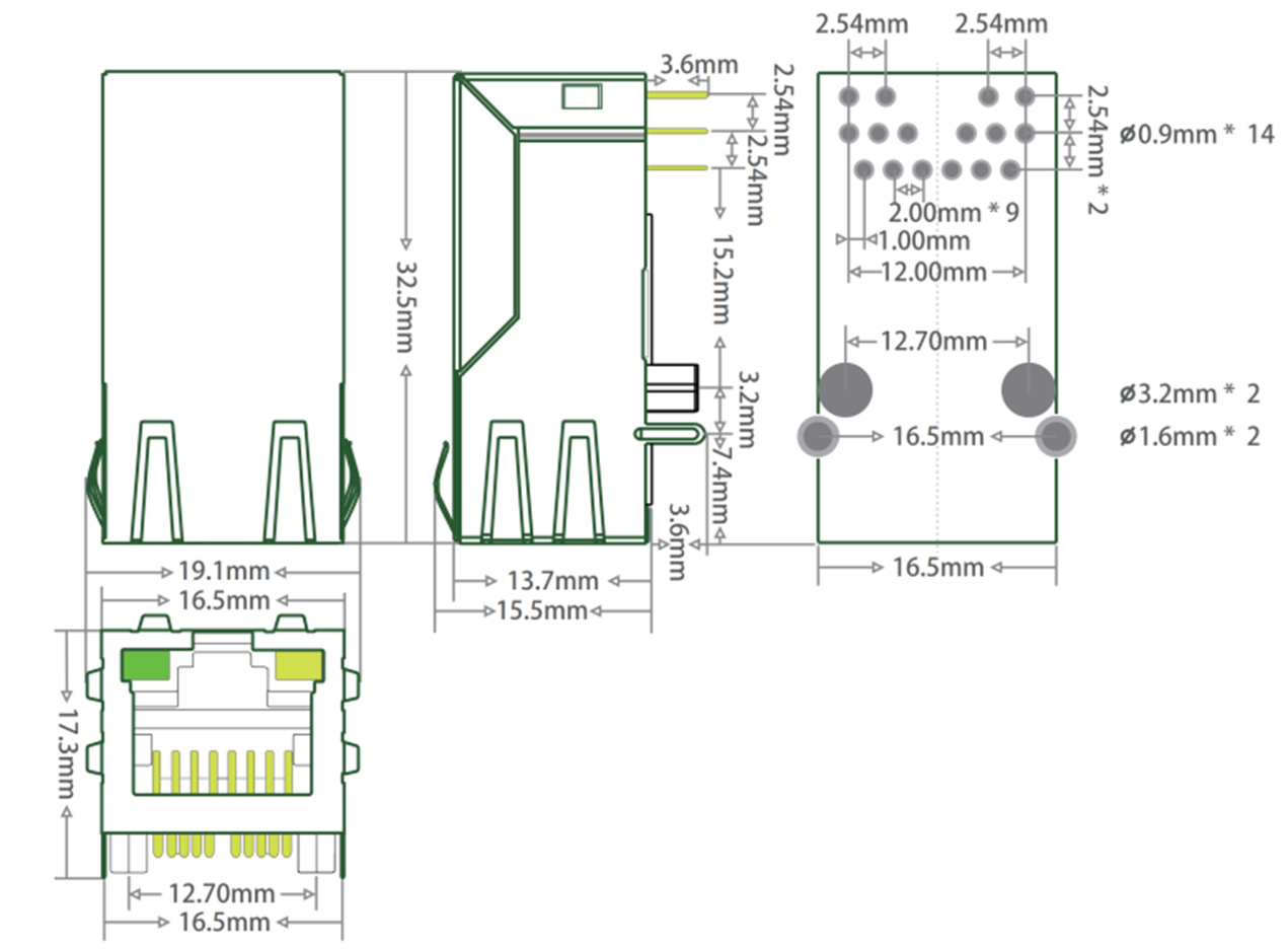
- Form factor: Plug-in Port module
- Pin pitch: 2.54 mm
- Dimensions: 32.5 × 16.5 mm