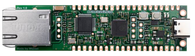
W6300-EVB-Pico2
Overview
W6300-EVB-Pico2 is a microcontroller evaluation board based on the Raspberry Pi RP2350 and fully hardwired TCP/IP controller W6300 – and basically works the same as Raspberry Pi Pico board but with additional Ethernet via W6300.
- Raspberry Pi Pico2 Clone
- Ethernet (W6300 Hardwired TCP/IP CHIP)
Revision history
| Date | Version | Description |
|---|---|---|
| May 2025 | 1.0 | Initial board release |
Features
-
RP2350 Microcontroller with Integrated 16Mbit Flash
- Symmetric dual Arm Cortex-M33 cores at up to 150MHz
- 520kByte multi-bank high performance SRAM
- External Quad-SPI Flash with eXecute In Place (XIP) capabilities
- Enhanced performance full-crossbar bus fabric
- Up to 48 multi-function General Purpose IO (8 can be used for ADC on RP2350-B)
- 1.8-5.0V IO Voltage
-
Security Features
- One Time Programmable (OTP) Memory: Used for boot configuration and secure key storage.
- Secure Boot: Ensures that only authenticated software can run on the device, utilizing OTP for key verification.
- Arm TrustZone Technology: Provides hardware isolation between secure and non-secure software, enhancing security for critical applications.
-
Analog and Digital Peripherals
- 12-bit 500ksps Analogue to Digital Converter (ADC)
- 2 × UART, 2 × I2C, 2 × SPI, 16 × PWM channels
- 1 × Timer with 4 alarms, 1 × Real Time Counter
- 3 × Programmable IO (PIO) blocks, 12 state machines total
- Flexible, user-programmable high-speed IO
- Can emulate interfaces such as SD Card and VGA
-
W6300 Ethernet Controller
- Support Hardwired TCP/IP Protocols : TCP, UDP, IPv6, IPv4, ICMPv6, ICMPv4, IGMP, MLDv1, ARP, PPPoE
- Support IPv4/IPv6 Dual Stack
- Support 8 independent SOCKETs simultaneously with 64KB Memory
- Support SOCKET-less Command: ARP, PING, ICMPv6(PING, ARP,DAD,NA,RS) Command for IPv6 Auto-configuration& Network Monitoring
- Support Ethernet Power Down Mode & System Clock Switching for power save
- Support Wake on LAN over UDP
- Support Serial & Parallel Host Interface: High Speed QSPI(MODE 0/3), System Bus with 2 Address signal & 8bit Data
- Internal 32Kbytes Memory for TX/ RX Buffers(total 64Kbytes Memory)
- 10BaseT / 10BaseTe / 100BaseTX Ethernet PHY Integrated
- Support Auto Negotiation (Full and half duplex, 10 and 100-based )
- Support Auto-MDIX only on Auto-Negotiation Mode
- Not support IP Fragmentation
- 3V operation with 5V I/O signal tolerance
- Network Indicator LEDs (Full/Half Duplex, Link, 10/100 Speed, Active)
- 48 Pin LQFP & QFN Lead-Free Package
-
Connectivity
- C-Type USB port for power and data (and for reprogramming the Flash)
- 40 pin 21x51 'DIP' style 1mm thick PCB with 0.1" through-hole pins also with edge castellations
- 3-pin ARM Serial Wire Debug (SWD) port
-
Networking
- 10 / 100 Ethernet PHY embedded
- Supports Auto Negotiation
- Full / Half Duplex(10 / 100 Based)
- Built-in RJ45(RB1-125BAG1A)
-
Power Supply
- Built-in Switch-mode DC-DC converter (replacing LDO for enhanced power efficiency)
Hardware Specification
Pin-out v1.0
PIN-OUT IMAGE COMMING SOON
W6300-EVB-Pico2 pinout is directly connected to the GPIO of RP2350 as shown in the picture above. It has the same pinout as the Raspberry Pi Pico2 board. However, GPIO15, GPIO16, GPIO17, GPIO18, GPIO19, GPIO20, GPIO21, GPIO22 are connected to W6300 inside the board. These pins enable QSPI communication with W6300 to use the Ethernet function. If you are using the Ethernet function, these pins cannot be used for any other purpose.
The RP2350 GPIO used inside W6300-EVB-Pico is as follows.
| I/O | Pin Name | Description |
|---|---|---|
| O | GPIO15 | Connected to INTn on W6300 |
| O | GPIO16 | Connected to CSn on W6300 |
| O | GPIO17 | Connected to SCLK on W6300 |
| I/O | GPIO18 | Connected to IO0 (MOSI) on W6300 (QSPI) |
| I/O | GPIO19 | Connected to IO1 (MISO) on W6300 (QSPI) |
| I/O | GPIO20 | Connected to IO2 on W6300 (QSPI) |
| I/O | GPIO21 | Connected to IO3 on W6300 (QSPI) |
| O | GPIO22 | Connected to RSTn on W6300 |
| I | GPIO24 | VBUS sense - high if VBUS is present, else low |
| O | GPIO25 | Connected to user LED |
| I | GPIO29 | Used in ADC mode (ADC3) to measure VSYS/3 |
QSPI Mode IO Lines
The IO lines for each QSPI mode are as follows.
| Mode | I/O | Pin Name | Description |
|---|---|---|---|
| Single | O | GPIO18 | Connected to IO0 (MOSI) on W6300 |
| Single | I | GPIO19 | Connected to IO1 (MISO) on W6300 |
| Mode | I/O | Pin Name | Description |
|---|---|---|---|
| Dual | I/O | GPIO18 | Connected to IO0 on W6300 (Dual Mode) |
| Dual | I/O | GPIO19 | Connected to IO1 on W6300 (Dual Mode) |
| Mode | I/O | Pin Name | Description |
|---|---|---|---|
| Quad | I/O | GPIO18 | Connected to IO0 on W6300 (Quad Mode) |
| Quad | I/O | GPIO19 | Connected to IO1 on W6300 (Quad Mode) |
| Quad | I/O | GPIO20 | Connected to IO2 on W6300 (Quad Mode) |
| Quad | I/O | GPIO21 | Connected to IO3 on W6300 (Quad Mode) |
Apart from GPIO and ground pins, there are 7 other pins on the main 40-pin interface:
| Pin No. | Pin Name | Description |
|---|---|---|
| PIN40 | VBUS | Micro-USB input voltage, connected to micro-USB port pin 1. Nominally 5V. |
| PIN39 | VSYS | Main system input voltage, which can vary in the allowed range 4.3V to 5.5V, and is used by the on-board LDO to generate the 3.3V . |
| PIN37 | 3V3_EN | Connects to the on-board LDO enable pin. To disable the 3.3V (which also de-powers the RP2350 and W6300), short this pin low. |
| PIN36 | 3V3 | Main 3.3V supply to RP2350 and W6300, generated by the on-board LDO. |
| PIN35 | ADC_VREF | ADC power supply (and reference) voltage, and is generated on W6300-EVB-Pico2 by filtering the 3.3V supply. |
| PIN33 | AGND | Ground reference for GPIO26-29. |
| PIN30 | RUN | RP2350 enable pin, To reset RP2350, short this pin low. |
Operation Condition
| Item | Description |
|---|---|
| Operation Temperature MAX | 85C (including self-heating) |
| Operation Temperature MIN | -20C |
| VBUS | DC 5V (+/- 10%) |
| VSYS Min | DC 4.3V |
| VSYS Max | DC 5.5V |
Recommended maximum ambient temperature of operation is 70C.
Technical Reference
RP2350 Datasheet
W6300 Datasheet
Schematic v1.0
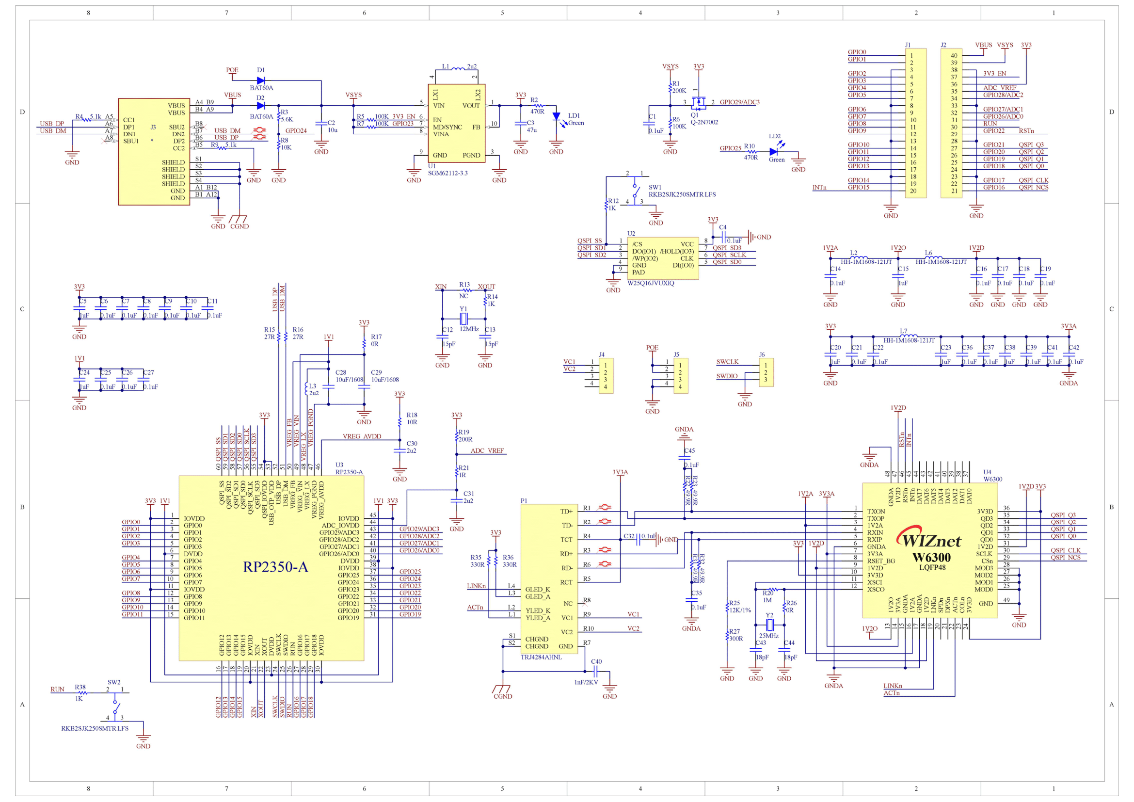
Schematic & Part list & Gerber File
3D File
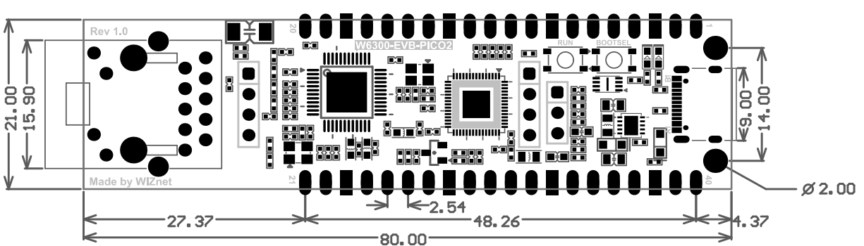
Dimension v1.0 (Unit : mm)
Firmware Example
Please refer to below links to find firmware example.
C/C++
Certification
CE
FCC
How to buy
![]()
![]()