Quick Start Guide
WizFi310 Evaluation Board
The WizFi310 EVB is the evalution board for testing WizFi310 and prototyping development. WizFi310 EVB is composed of a WizFi310 evalution board and WizFi310 module.
Feature Identification
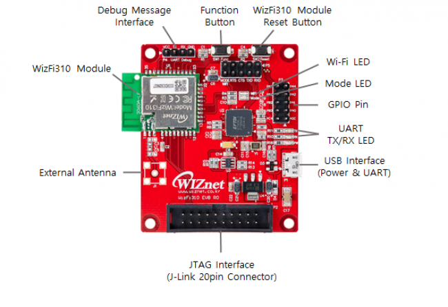
Button Description
| WizFi310 Reset | Through this button, user can restart WizFi310 module. |
| Function | Through the function button, user can enter specific mode without AT Command.♦ AP Mode : When module is working, press it once.♦ OTA Mode : When module is working, press it twice.♦ Factory Default : When module is working, press it three times. |
LED Description
| UART RX/TX | Indicate UART RX/TX Status |
| Power LED | Indicate Power On/Off of WizFi310 |
| Mode LED | Indicate Data/Command Mode ♦ LOW(ON) : Data Mode ♦ HIGH(OFF) : Command Mode |
| Wi-Fi LED | Indicate Wi-Fi Association ♦ LOW(ON) : Wi-Fi is associated ♦ HIGH(OFF) : Wi-Fi is not associated |
Pin Description
| GPIO Pin | Through this pin, user can use GPIO signal |
|---|
Interface Description
| Debug Message Interface | Through these pins, user can see debug message.Using these pins, WizFi310 can't use AT commands. |
| USB Interface | This provides power supply & Serial interface .Default serial information:♦ Baud rate : 115200 ♦ Data rate : 8 ♦ Stop bits : 1 ♦ Parity : None ♦ Flow control : None |
| JTAG Interface | User doesn't need to know. It is used only for factory. |
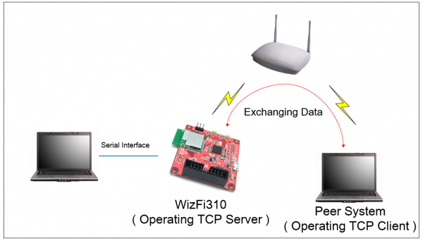
Start Serial to Wi-Fi
This chapter describes how to set WizFi310 in order to exchange data with peer system. This picture shows the environment for testing Serial to Wi-Fi example. In this example, WizFi310 is set to TCP server and peer system is set to TCP client. And then data can be exchanged between WizFi310 and the peer system.
Using Serial Command
This section explains how to connect to AP by using serial command. The default value which module will start is command mode, so users can input AT command. If you input the AT commands as below, WizFi310 will connect to AP and then start TCP server. In the example, AP is set like as such. ( SSID : WizFiDemoAP, Security : WAP2, Key : 12345678 )
AT (Sent AT command with 0x0d (Hex of Enter button)) [OK] (response meaning successful execution)
AT+WSET=0,WizFiDemoAP (AT command for setting WiFi association) [OK]
AT+WSEC=0,,12345678 (AT command for setting WiFi security) [OK]
AT+WNET=1 (AT command for setting DHCP) [OK]
AT+WJOIN (AT command executing AP association) Joining : WizFiDemoAP Successfully joined : WizFiDemoAP
[Link-Up Event] IP Addr : 192.168.3.104 Gateway : 192.168.3.1 [OK]
AT+SCON=SO,TSN, , ,5000,1 (AT command for setting TCP Server) [OK]
[CONNECT 0] (When TCP connection is done, it shows this message)
If it is done successfully, Mode LED will be on because WizFi310 is set to < data mode >. For more detailed information about < data mode >, refer to 🌎Command mode & Data mode In order to exit data mode or enter into command mode again, You have to send a single '+++' string without CR or LF (0x0D, 0x0A) - just the three (0x2B = '+') characters.
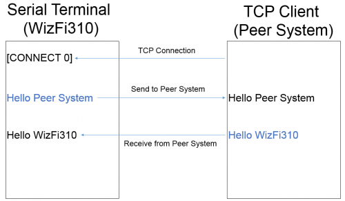
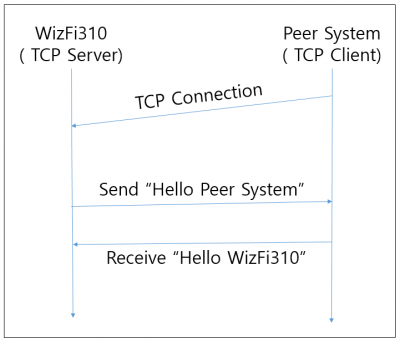
Exchanging data with a peer system
This section explains how to exchange data between WizFi310 and Peer System. This picture describes the flow for data communication.
After TCP connection is done successfully and then if WizFi310 receives serial data, the serial data will be sent to peer system immediately. And WizFi310 can receive data from peer system.