WizFi310 Datasheet v0.0.0 - English
Datasheet History
| Version | Date | Description |
|---|
| V0.0.0 | 2016-05-20 | release version |
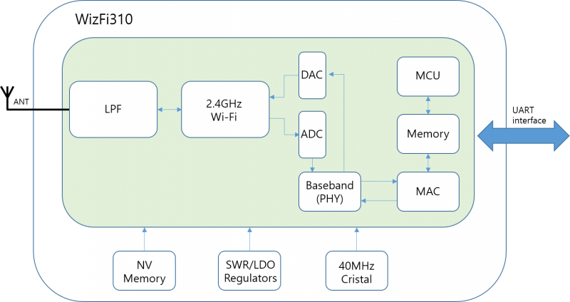
WizFi310 is a small size wireless module for the highest level of integration, featuring 802.11b/g and 802.11n.
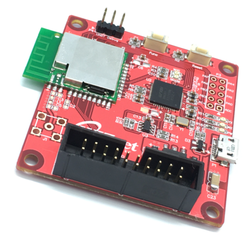
It has an onboard antenna, and an external antenna interface, RF output PIN also exists in the board.
WizFi310 internally integrated TCP / IP protocol stack, supporting numerous protocols such as ARP, IP, ICMP, TCP, UDP, DHCP CLIENT, DHCP SERVER, DNS and other etc. It supports AP mode, Station mode. It also support rich AT commands for most kinds of application needs. Users can easily and quickly use it on wifi networking and data transmission. The baud rate of module serial port up to 921600bps, which can fully meet on low-rate applications.
In the networking part, WizFi310 supports network parameters storage in the module that reduces time to connect to a network. It also supports WPS. For application protocols, MQTT and SSL were supported in this module.
For software and driver development, WIZnet provides extensive technical documents and reference software codes for system integration.
- Application
- UART serial AT command set operation
- Support for multiple baud rate
- Support wireless configuration and OTA firmware upgrade
- Support on fast networking application functions (WPS function)
- Support MQTT, GMMP, TLS applications protocols
- Standards Supported
- 802.11b/g/n compatible WLAN
- Light Weight TCP/IP protocol
- WPA, WPA2, Open, shared key
- WPS support
- WLAN MAC Features
- CMOS MAC, Baseband PHY, and RF in a single chip for 802.11b/g/n compatible WLAN
- Complete 802.11n solution for 2.4GHz band
- 72.2Mbps receive PHY rate and 72.2Mbps transmit PHY rate using 20MHz bandwidth
- 150Mbps receive PHY rate and 150Mbps transmit PHY rate using 40MHz bandwidth
- PHY-level spoofing to enhance legacy compatibility
- Power saving mechanism
- WLAN PHY Features
- 802.11n OFDM
- One Transmit and one Receive path (1T1R)
- Short Guard Interval (400ns)
- DSSS with DBPSK and DQPSK, CCK modulation with long and short preamble
- Maximum data rate 54Mbps in 802.11g and 150Mbps in 802.11n
- Fast receiver Automatic Gain Control (AGC)


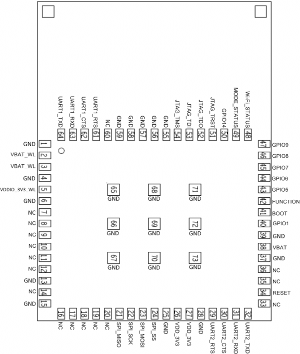
| No | Name | Type | Description |
|---|
| 1 | GND | - | Ground |
| 2 | RF_OUT | - | 2.4GHz RF output |
| 3 | GND | - | Ground |
| 4 | VDDIO | - | 3.3V for Digital IO or Digital blocks |
| 5 | JTAG_CLK | - | For normal operation, if JTAG is not used, this pin can be left unconnected (NC) |
| 6 | JTAG_TMS | - | For normal operation, if JTAG is not used, this pin can be left unconnected (NC) |
| 7 | JTAG_TDO | - | For normal operation, if JTAG is not used, this pin can be left unconnected (NC) |
| 8 | JTAG_TDI | - | For normal operation, if JTAG is not used, this pin can be left unconnected (NC) |
| 9 | JTAG_TRST | - | For normal operation, if JTAG is not used, this pin can be left unconnected (NC) |
| 10 | NC(ADC) | - | - |
| 11 | Reset | - | Module reset pin(Active low) |
| 12 | NC(GPIOA0) | - | Ground |
| 13 | NC(GPIOA1) | - | - |
| 14 | NC(GPIOA2) | - | - |
| 15 | Mode LED | - | - |
| 16 | NC(GPIOA4) | - | - |
| 17 | WiFi LED | - | - |
| 18 | NC(GPIOA7) | - | - |
| 19 | NC(GPIOA6) | - | - |
| 20 | GND | - | Ground |
| 21 | GND | - | Ground |
| 22 | VCC 3.3V | - | 3.3V power supply |
| 23 | TXD | - | Serial data communication interface send |
| 24 | RTS | - | Serial flow control pin, ready to receive data/request the other party to send data (Active low) |
| 25 | CTS | - | Serial flow control pin, ready to send data/request each other to send data (Active low, High level cannot send/Low level can send data) |
| 26 | RXD | - | Serial data communication interfece receive |
| 27 | NC(GPIOC7) | - | - |
| 28 | FUNC | - | - |
| 29 | NC(GPIOB3) | - | - |
| 30 | NC(GPIOB2) | - | - |
| 31 | LOG RX | - | - |
| 32 | LOG TX | - | - |
| 33 | GND | - | Groun |
| 34 | NC | - | - |
| 35 | NC | - | - |
| **ITEMS | CONTENTS** |
|---|
| Operating frequency | 2.400 ~ 2.4835Ghz |
| WiFi standard | 802.11b/g/n |
| Modulation | 11b: DBPSK,DQPSK and CCK and DSSS,11g: BPSK,QPSK16Qam,64QAM and OFDM, |
| 11n: MCSO-15 OFD | |
| Data rates | 11b: 1,2,5.5 and 11Mbps,11g:6,9,12,18,24,36,48, and 54Mbps,11n:MCSO-15, up to 150Mbps |
| Host interface | UART |
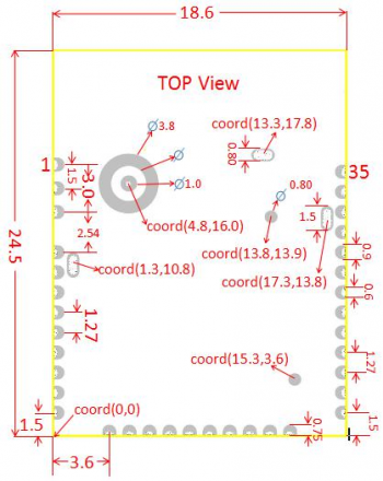
| Dimensions | Typical (L x W): 21mm x 18mm |
| Operation Temperature | -20°C to +85°C |
| Storage Temperature | -55°C to +125°C |
| Operation Voltage | 3.3V±0.2V |
| ITEMS | CONTENTS |
|---|
| Specification | IEEE802.11g |
| Mode | OFDM |
| Channel | CH1 to CH13 |
| Data rate | 6, 9, 12, 18, 24, 36, 48, 54Mbps |
| Power level(calibrated) | Minimum | Typical | Maximum | Unit | Note |
|---|
| 16dBm Target(For each antenna Port) | 12 | 14 | 16 | dBm | |
| Constellation error(EVM)@target power | Minimum | Typical | Maximum | Unit | Note |
|---|
| 54Mbps | - | -30 | -28 | dB | |
| Frequency error | -25 | 0 | +25 | kHz | |
| Minimum input level sensitivity | Minimum | Typical | Maximum | Unit | Note |
|---|
| 54Mbps | - | -78 | - | dBm | |
| Maximum input level(PER ≤ 10 %) | - | -10 | - | dBM | |
| ITEMS | CONTENTS |
|---|
| Specification | IEEE802.11n HT20 @2.4Ghz |
| Mode | OFDM |
| Channel | CH1 to CH13 |
| Data rate | MCS0/1/2/3/4/5/6/7/8/9/10/11/12/13/14/15 |
|Power level(calibrated)| Minimum| Typical |Maximum| Unit.| Note.|
|---------------------------------|-----|---------|------|------|
|16dBm Target(For each antenna Port)| 12|14| 16| dBm| |
| Constellation error(EVM)@target power | Minimum | Typical | Maximum | Unit | Note |
|---|
| MCS7 | - | -30 | -28 | dB | |
| Frequency error | -25 | 0 | +25 | kHz | |
| Minimum input level sensitivity | Minimum | Typical | Maximum | Unit | Note |
|---|
| MCS7(PER ≤ 10 %) | - | -76 | - | dBm | |
| Maximum input level(PER ≤ 10 %) | - | -10 | - | dBM | |
| ITEMS | CONTENTS |
|---|
| Specification | IEEE802.11n HT40 @2.4Ghz |
| Mode | OFDM |
| Channel | CH1 to CH13\ |
| Data rate | MCS0/1/2/3/4/5/6/7/8/9/10/11/12/13/14/15 |
| Power level(calibrated) | Minimum | Typical | Maximum | Unit | Note |
|---|
| 16dBm Target(For each antenna Port) | 12 | 14 | 16 | dBm | |
| Constellation error(EVM)@target power | Minimum | Typical | Maximum | Unit | Note |
|---|
| MCS7 | - | -30 | -28 | dB | |
| Frequency error | -25 | 0 | +25 | kHz | |
| Minimum input level sensitivity | Minimum | Typical | Maximum | Unit | Note |
|---|
| MCS7(PER ≤ 10 %) | - | -74 | - | dBm | |
| Maximum input level(PER ≤ 10 %) | - | -10 | - | dBM | |
| ITEMS | CONTENTS |
|---|
| Specification | NVM Flash |
| Space | 160KByte |
| Operate write times | Total 10000 times |
Note: NVM flash is used to store user configuration or firmware, do not use to store these often changed configuration or user data.
| State | Current(3.3V) | Description |
|---|
| Deep Sleep | 5.5uA | Low Power Timer and GPIO Event Wake up |
| Deep Standby | 25uA | Low Power Timer and GPIO Event Wake up |
| Associated Idle(DTIM=1) | 3.3mA | Associated with AP but no traffic |
| Associated Idle(DTIM=2) | 2.41mA | Associated with AP but no traffic |
| Associated Idle(DTIM=3) | 1.98mA | Associated with AP but no traffic |
| Sleep | 0.5mA | Associated with AP but no traffic |
| Run in active clock | 25mA | CPU full run, UART available,WiFi is disable |
| 11n RX mode | 62mA | CPU full run, UART available,WiFi is in 11n RX |
| 11n TX mode@13dBm | 162mA | CPU full run, UART available,WiFi is in 11n TX |
| Peak current | 240mA | CPU full run, UART available,WiFi is in 11n TX |

| Type | Thickness (Height) |
|---|
| with CAN | 3.15 (+/-) 0.15mm |
WizFi310 Ref.Schematic 


