Getting Started-[EN]
Supported Languages

** This document is based on the use of the WIZSPE-T1L evaluation board. **
Unpacking the WIZSPE-T1L
What's in the Box?
The WIZSPE-T1L evaluation board package contains the following parts:
- WIZSPE-T1L Module
Device Layout
TBD (img)
Parts
- Ethernet MCU W7500 based on ARM Cortex-M0 with an integrated Hardwired TCP/IP core
- PHY (10Base T1L Ethernet Transceiver) capable of communication up to 1.2 km over 2 wires (1 pair)
- Pluggable Terminal Block for easy wiring
- Pin to switch from App mode to Boot mode
- Pin to switch from App mode to AT command mode
- SWD(JTAG) used as hardware debug port
- Pin for ISP mode/debug log monitoring
- Reset Button
- Reset IC
- DC-DC converter supporting wide input voltage (5VDC – 36VDC)
- 2pi DC-JACK
- Power supply through data line available (PoDL module sold separately)
Interfaces and Ports
- Data port (UART): PIN Header
- Network port: Terminal block
- User optional port: 1x6 2.54mm Pin header (Debug(ISP Port))
Prerequisites for Setup
Software
- Configuration Tool program (v1.5.7.2 or higher) (Download)
- TCP server / TCP client / UDP terminal program
- Serial terminal program
Hardware
- WIZSPE-T1L Module
- Power supply for operation
- 5V – 36V DC adapter
- With optional WIZPoDL module, can be powered from PoDL PSE
Connect Your WIZSPE-T1L
WIZSPE-T1L Factory Settings
| Network Settings | Device | IP Address | 192.168.11.2 | - |
|---|---|---|---|---|
| ::: | ::: | Gateway | 192.168.11.1 | - |
| ::: | ::: | Subnet Mask | 255.255.255.0 | - |
| ::: | ::: | DNS Server | 8.8.8.8 | Google Public DNS |
| ::: | ::: | Port | 5000 | - |
| ::: | Remote | IP Address | 192.168.11.3 | - |
| ::: | ::: | Port | 5000 | - |
| Serial Port Settings | Data UART | 115200-8-N-1 / Flow Control: None | - |
|---|---|---|---|
| ::: | Debug UART | 115200-8-N-1 / Flow Control: None | Fixed |
-
Default operation mode: TCP Server Mode
-
Debug messages: Enabled
-
Serial command mode switching: Enabled
-
Serial command mode switch code: +++ (3-byte hex code, [2B][2B][2B])
-
Data packing option – Time: Disabled
-
Data packing option – Size: Disabled
-
Data packing option – Char: Disabled
-
Inactivity timer: Disabled
-
Reconnection interval: 3 seconds
-
Keep-Alive packet transmission: Enabled, initial delay 7s, interval 5s
PC Settings
The PC or laptop used for configuring WIZSPE-T1L must be on the same Ethernet network segment for communication.
Example: PC Network Settings
* Example PC settings when WIZSPE-T1L is in factory default state:
| Network Settings | PC | IP Address | 192.168.11.3 | - |
|---|---|---|---|---|
| ::: | ::: | Gateway | 192.168.11.1 | - |
| ::: | ::: | Subnet Mask | 255.255.255.0 | - |
| ::: | ::: | Port | 5000 | - |
-
For testing TCP client and mixed TCP server/client mode, it is recommended to match the WIZSPE-T1L’s Remote host settings with the PC (or laptop).
-
When using DHCP (automatic IP allocation), both the WIZSPE-T1L and the PC must receive IP addresses from the same router.
Connecting Steps
The WIZSPE-T1L is designed to connect with serial devices via UART. For initial testing with a PC, you will need a UART to USB converter so that the module can communicate with the PC via serial interface.
Step 1: Plug in
After assembling the WIZSPE-T1L module with the evaluation board, connect as follows:
-
10BASE-T1L Ethernet Cable
- Connect the P and N of 10Base-T1L to the terminal block of the WIZSPE-T1L module. (Since polarity is detected and corrected, it does not matter if P and N are connected in reverse.)
- It is recommended to use twisted cables such as UTP cable or RS485 cable. Depending on the type of cable used, the maximum communication distance may vary (700 m – 1200 m).
-
Serial Cable
- Connect the J11 (UART port) of the WIZSPE-T1L module to the PC using a UART-to-USB module. The UART-to-USB module can be purchased from commercially available products.
Step 2: Power on
Connect a 5V – 36V adapter or WIZPoDL (optional) to the PSE.
- When powered correctly, the power LED (red) on the module and board will light up.
Step 3: Search
Run the Configuration Tool on the PC and click the Search button. If the board is powered and connected to the same network, the tool will display the WIZSPE-T1L module’s MAC address and configuration values.
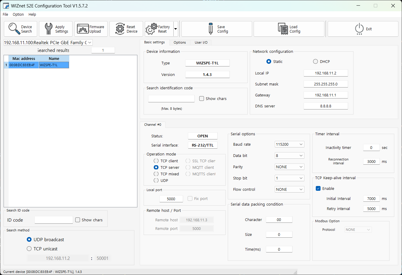 |
| Figure: WIZnet Configuration Tool |
Step 4: Set up your WIZSPE-T1L
Adjust the device settings according to your environment. For this step, initial testing is based on factory default values.
* After changing the settings in the Configuration Tool, you must click the Setting button to apply the changes.
Step 5: Connect
Use the PC as a serial device and TCP client to perform data communication testing. For this, a serial terminal program and a TCP client terminal program must be running on the PC. Based on the factory default settings, connect the PC and the device after configuring each program as follows.
- Serial terminal program: 115200-8-N-1, Flow control: None
- TCP client program: 192.168.11.2:5000 (IP address and port of WIZSPE-T1L)
The COM port for connecting the serial terminal program can be checked in the Windows Control Panel > Device Manager.
- Control Panel > System > Device Manager
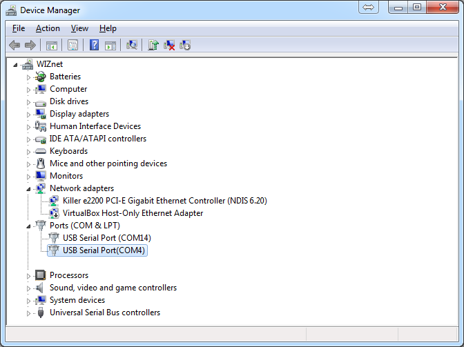 |
| Figure: Device Manager |
Step 6: Verify
If the following data communication works correctly, the basic data transmission function of WIZSPE-T1L is verified:
-
Serial to Ethernet: Transmission verification
- Enter a string in the serial terminal. The same string should appear on the TCP client terminal.
-
Ethernet to Serial: Transmission verification
- Enter a string in the TCP client terminal. The same string should appear on the serial terminal.
Step 7: Done
Now you are ready to use the WIZSPE-T1L!
-
This section describes the process of testing the operation of the WIZSPE-T1L product, assuming the PC is used as a serial device and a remote network device.
-
Afterward, the user can connect the WIZSPE-T1L module to the serial device where networking functions will be added, and control or monitor the device through data transmission and reception from a remote PC or server (remote network device).
Documents History
| Title | Description | Link | Notes |
|---|---|---|---|
| Getting-Started | Ver 1.0.0 (250919) | - |