Datasheet
Hardware Specification
Product Spec Table
| Category | Description | |
|---|---|---|
| MCU | ARM Cortex-M3 Core | W55MH32 1. 32-bit Arm® Cortex®-M3 Core 2. 216MHz maximum frequency 3. Flash: 1024KB 4. 96K bytes of SRAM |
| Hardwired TCP/IP Core | 1. 8 independent Sockets 2. SRAM for socket: 32KB 3. TCP/IP Protocols: TCP, UDP, ICMP, IPv4, ARP, IGMP, PPPoE | |
| Serial | Interface | WIZ-IP32: 2 x TTL |
| Signal | TXD, RXD, GND | |
| Parameters | 1. Parity: None, Odd, Even 2. Data bits: 7, 8 bit 3. Flow control: None | |
| Baud Rate Speed | 1200 bps to 1,152,000 bps | |
| Dimension | L x W x H | WIZ-IP32: 32.5mm x 16.5mm x 13.70mm |
| Connector type | WIZ-IP32: 2.54mm Pitch 16 Pin-header | |
| Input Voltage | WIZ-IP32: DC 3.3V | |
| Temperature | -40℃ ~ 85℃ (Operation), -50℃ ~ 95℃, 5 ~ 95% (Storage range) |
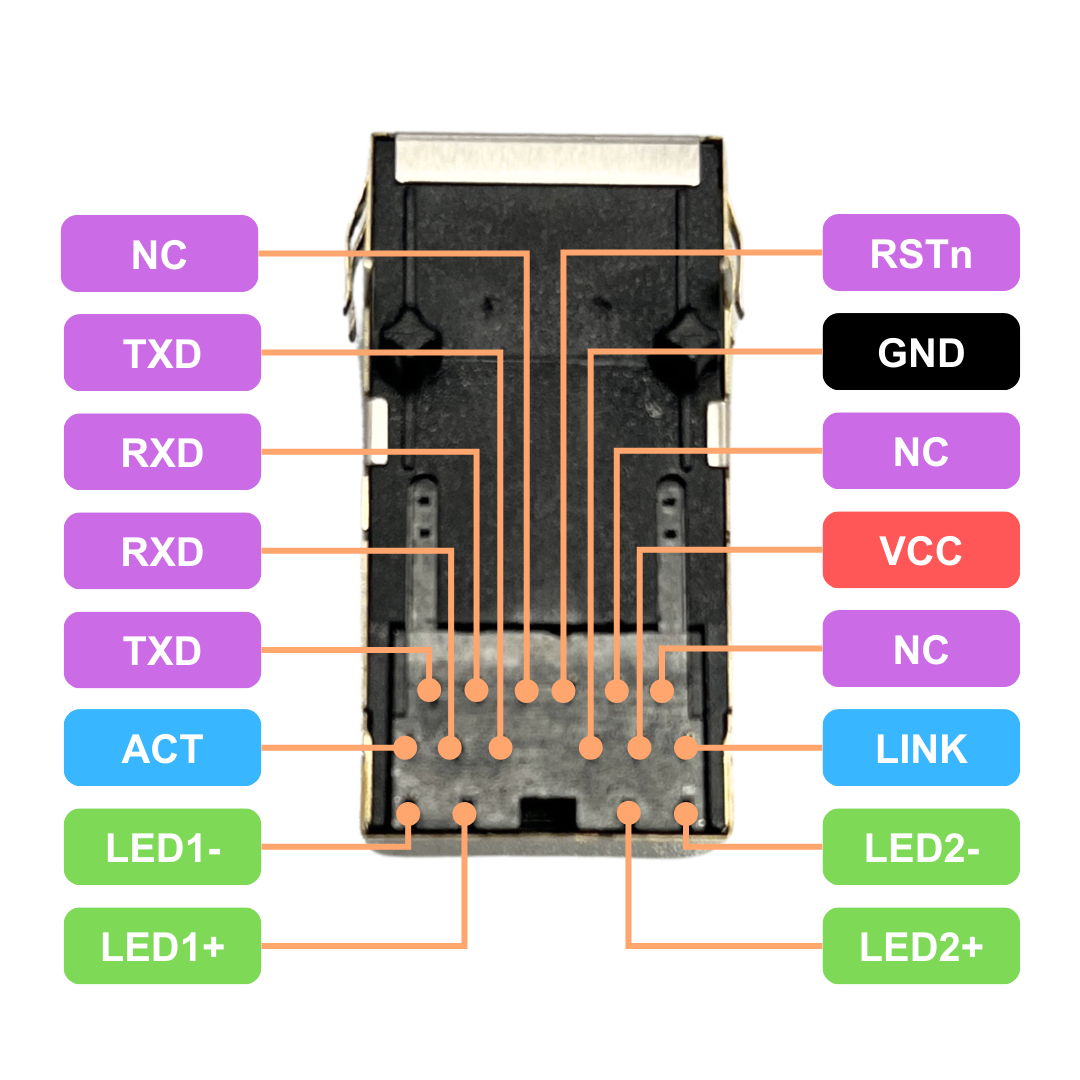
WIZ-IP32 Pinout
 |
WIZ-IP-EVB Board
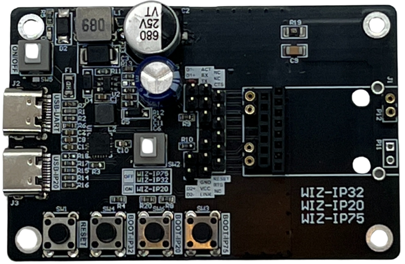 |
- WIZ-IP32, WIZ-IP75 WIZ-IP20 Developer board
- RJ45 with external LED status
- Type C USB Power supply and serial communication
- Power Source selection Pin header
- External Pin headers for module debug testing
- On/OFF, module selection and Reset buttons
WIZ-IP-EVB Board Pinout
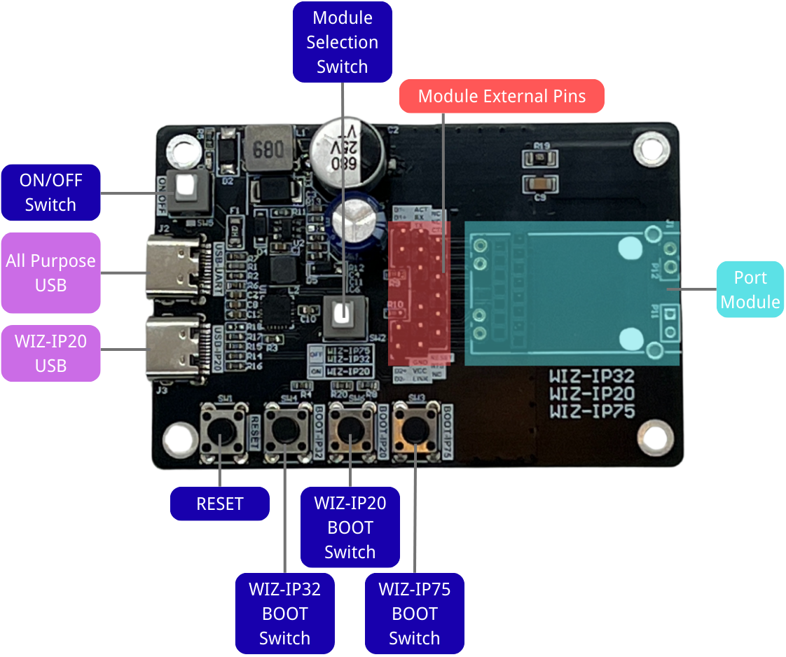 |
WIZ-IP-EVB Board pin assignments
 |
RJ45 (J5) Interface Pin Assignments
| Pin | Signal | Pin Type | Description |
|---|---|---|---|
| 1 | D1- | RJ45_LED | The negative pole of the RJ45 connection status LED is connected to the ACT pin in default. |
| 2 | ACT | RJ45_LED Control Pin | RJ45 Interface data status LED. |
| 3 | TXD | Serial Port 1 | 3.3V TTL serial port 1 transmit pin. |
| 4 | D1+ | RJ45_LED | The positive pole of the RJ45 connection status LED is connected to 3.3V power supply in default. |
| 5 | RXD | Serial Port 2 | 3.3V TTL serial port 2 receive pin. |
| 6 | RXD | Serial Port 1 | 3.3V TTL serial port 1 receive pin. |
| 7 | TXD | Serial port 2 | 3.3V TTL serial port 2 transmit pin. |
| 8 | NC | - | - |
| 9 | GND | Power Ground | Module power ground |
| 10 | RESET | Reset Pin | The entire module is reset when a low - level signal is received. |
| 11 | D2+ | RJ45_LED | The positive pole of the RJ45 data status LED is connected to the 3.3V power supply in default. |
| 12 | VCC | Power Supply Pin | Power supply - Default DC 3.3V |
| 13 | NC | - | - |
| 14 | D2- | RJ45_LED | The negative pole of the RJ45 data status LED is connected to the LINK pin in default. |
| 15 | LINK | RJ45_LED Control Pin | RJ45 Interface connection status LED. |
| 16 | NC | - | - |
Schematic
WIZ-IP32
| H/W version | Module | File Type | Link | Remarks |
|---|---|---|---|---|
| 1.2 | WIZ-IP32 | Lastest H/W version |
Electrical Characteristics
Operating Conditions
The following tables show the voltage and current under 25 °C environment
| Symbol | Parameter | Module | type | Min | Typ | Max | Unit |
|---|---|---|---|---|---|---|---|
| Vin | Module Voltage | WIZ-IP32 | Voltage Input | 3.0 | 3.3 | 3.6 | V |
| Iin | Module Current | WIZ-IP32 | Current Input | 92.8 | 102.5 | 155.0 | mA |
| - | Module Current | WIZ-IP32 | Standby Current | - | 92.8 | - | mA |
| - | Module Current | WIZ-IP32 | Normal communication | - | 155.0 | - | mA |