WIZS2E Config Tool software configuration
WIZS2E Config Tool is an upper computer configuration software that runs on the Windows operating system and is compatible with WIZ-DTU, WIZ-IP32, W5500S2E and W7500S2E series serial to Ethernet modules. Users can easily search, view, and configure various functions and information of W5500S2E / W7500S2E serial to Ethernet module through WIZS2E Config Tool.
Note: Before configuring, it is recommended to turn off the firewall and ensure that all module IP addresses on the local area network do not conflict.Configuration Tool Layout
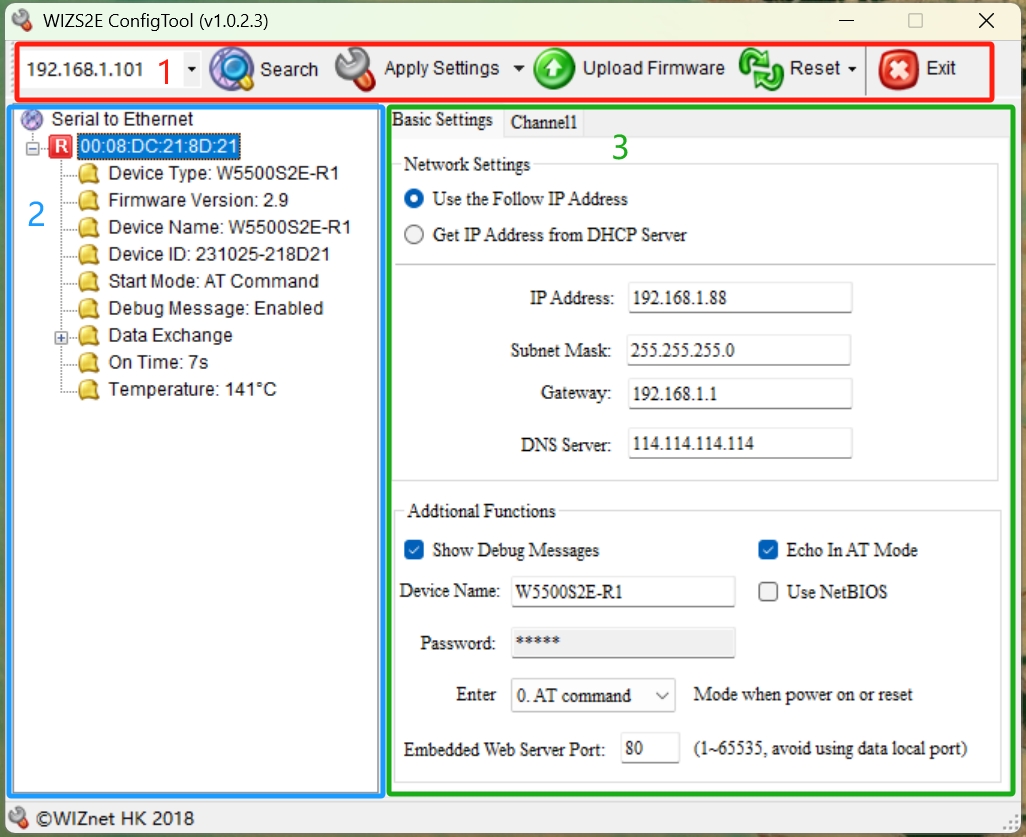 |
| Figure: Configuration Layout |
-
Icon Menu - Network interface configuration, Device Search, save settings, firmware upload and device reset
-
Device List - Listed all existing modules in the same local area network (LAN)
-
Module Configuration - All configuration settings of the module.
The W7500S2E series module includes Basic Settings and Channel1 configurations.
The following are the list for all configurables for W7500S2E modules.
Basic Settings Tab
| Network Settings | Description | Default |
|---|---|---|
| IP address Method | Selecting the IP address collection method | Use the follow IP Address |
| IP address | IP address of the module | 192.168.1.88 |
| Subnet Mask | Subnet Mask | 255.255.255.0 |
| Gateway | Gateway IP | 192.168.1.1 |
| DNS Server | DNS Server IP address | 114.114.114.114 |
| Addtional Functions | Description | Default |
|---|---|---|
| Show Debug Messages | Display debug message | Enable (checked) |
| Echo In AT Mode | Echo your inputs | Enable (checked) |
| Device Name | Set/Display the module name | Module Name |
| Use NetBIOS | Enable/Disable NetBIOS function | Disable (unchecked) |
| Password | Set the module's new password | admin |
| Entering Mode after power on or reset | "AT Command Mode" or "Data mode" | AT Command Mode |
| Embedded Web Server Port | Set/Display the HTTP port number | 80 |
Channel1 Tab
| COM Port Settings | Description | Default |
|---|---|---|
| Baud Rate | 1200 bps ~ 460800 bps | 115,200 |
| Data Bit | 7 or 8 bits | 8 |
| Stop Bit(S) | NONE, ODD or EVEN | NONE |
| Parity | 1 or 2 bits | 1 |
| Flow Control(F) | NONE or "CTS/RTS mode" or "RS485" | None |
| Serial Data Packaging Condition | Description | Default |
|---|---|---|
| Nagle Wait Time(ms) | Ethernet packets separate by time interval | 0 |
| Data Length | Ethernet packets separate by Data length | 0 |
| Connection | Description | Default |
|---|---|---|
| Work As | Socket operation mode (TCP Server/ TCP Client/ UDP) | TCP Server |
| Local Port | Local port number (0 ~ 65535, avoid used port) | 5000 |
| Bind Local Port | Only valid in TCP client mode | Disable (uncheck, locked) |
| Remote Host | Remote host IP address or domain name | 192.168.1.99 (locked) |
| Remote Port (Text box next to Remote Host) | Remote host port number | 5000 (locked) |
| Communication | Description | Default |
|---|---|---|
| Clean Data Buffer when TCP Connected | Clear Serial port buffer checkbox (work with Connect TCP Server) | Disable (uncheck) |
| Connect TCP Server when | Connect to a TCP Server when Power on or Serial data Received | Power On (locked) |
| Request Admin Password | Verification password for connection | Disable (uncheck) |
| Auto Message | Auto message from the module (first data package) | No message |
| Inactivity (ms) | TCP inactivity time | 0 |
| Reconnection (ms) | TCP reconnection time | 0 (locked) |
| Keep Alive (5s) | TCP keep alive time | 0 |
Icon Menu
| Figure: Configuration Icons |
1. Network Interface Selection - To solve the problem of not being able to determine whether the current module is a wired or wireless network card.
The following is an example of the module's network interface selection List
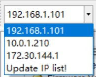 |
| Figure: Network Interface Selection list |
Users can first click "Update IP list!" to update the network card list, then select the corresponding network card to configure the module.
2. Search button  - Search all the listing modules within the same network and categorize by module's MAC address.
3. Apply Settings button  - It applies all your modified settings by pressing the button.
4. Upload Firmware button  - Upload a module application firmware bin file to the module
Procedure for uploading the firmware:
a) Set or select the network interface that has the same IP segment as the module
 |
| Figure: Same Segment IP address |
b) Select the correct Application firmware file for the module
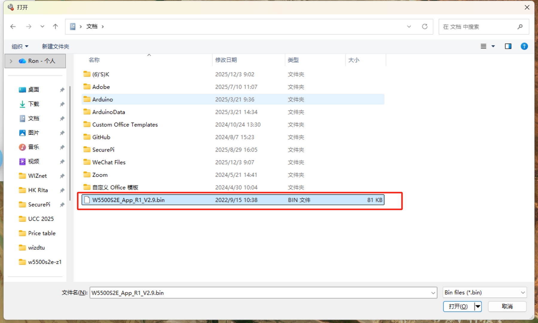 |
| Figure: Application firmware bin file |
c) Wait until the firmware upgrade progress is complete. It will pop up a window like the image below to show that the progress is over.
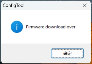 |
| Figure: Firmware download complete window |
4. Reset Button  - There are two sections for user to select.
a) Reset Now ![]() - Activates immediately without saving any configuration settings
- Activates immediately without saving any configuration settings
b) Factory Reset ![]() - Reset all the configurations back to default settings
- Reset all the configurations back to default settings
5. Exit Button  - Close the WIZSE configuration tools
Device List
Device list will show all the WIZSE modules within the same network segments. The following features can be used in this Device list .
a) Expand the module details - It has a "![]() " button next to the MAC address of the module to expand the details of the module.
" button next to the MAC address of the module to expand the details of the module.
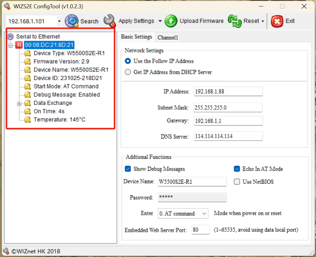 |
| Figure: Module details |
b) Right Click - If you right click on the device list, it shows extra features for expanding, collapsing, sorting or researching all the modules within the same network segment.
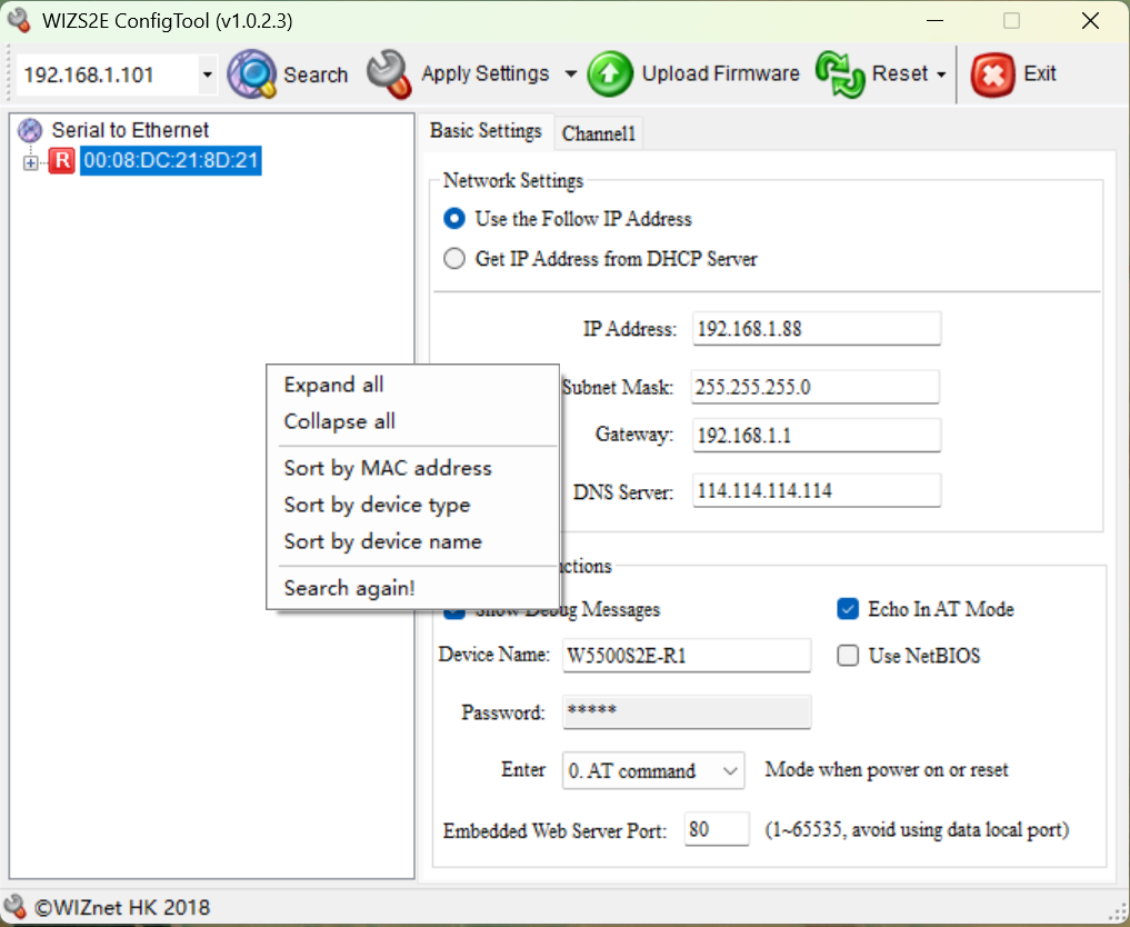 |
| Figure: Right click in device list |
Basic Settings
As shown in the following figure, these are the basic parameters for the W7500S2E series module, which is divided into two parts for explanation.
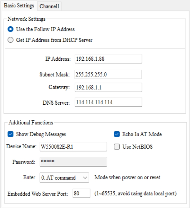 |
| Figure: Basic Settings |
Network Settings
-
IP Address Method- There are two options for user to choose.
- Use the Follow IP Address - Static IP mode and the module uses the IP information showed on the WIZSE configuration tools (Default)
- Get IP Address from DHCP Server - DHCP mode and the module IP address from the DHCP Server
-
IP Address- Module's IP Address. Default: 192.168.1.88
-
Subnet Mask - Module's Subnet Mask. Default: 255.255.255.0
-
Gateway - Module's Gateway IP address. Default: 192.168.1.1
-
DNS Server - DNS Server IP address. Default: 114.114.114.114
Note 2: The above IP information text box will display the DHCP assigned information when user has selected DHCP mode.
Additional Functions
-
Show Debug Message - Display module debugging information. Checking this option will print the module debugging information from the serial port. It is enabled by default.
-
Echo in AT Mode - Enable the AT command echo function. The echo function means that the W7500S2E module returns the input command exactly as it is to the serial port and then displays it on the serial port software interface. When users use the serial port software to configure the module, enabling the echo function helps users configure it conveniently. However, when using single-chip microcontrollers or other embedded devices to configure the module, enabling the echo function will cause problems. In this case, the echo function must be turned off. By default, this option is checked to enable the echo function.
-
Device Name - Set/Display the module name. It must consist of numbers, letters, or a combination of both, and cannot be empty. Case sensitivity is applied. The maximum length is 15 bytes. The default is the module name.
-
Use NETBIOS - Enable the NetBIOS function option. When checked, the NetBIOS function will be enabled. By default, it is not enabled. After enabling the NetBIOS function, users can directly access the built-in web page of W7500S2E series by entering "http:// module name" in the browser address bar.
-
Password - The current password for the module will not be displayed. User could change a new password directly without entering the previous password. The default password is "admin".
-
Entering Mode after power on or reset - The list box beneath password section. User could choose AT command or Data mode (Transparent transmission) after the module has turned on or reset. The default mode is AT command mode.
-
Embedded Web Server Port - Set/Display the port number of the Web server of W7500S2E series. The default is 80. It is not recommended to change it. The range of values is 0 to 65,535. If it is not set to 80, then it is required to add the web server port to the browser address bar. For example: 192.168.1.88:8000.
Channel1
As shown in the following figure, these are the TCP and Serial setups for W7500S2E series module, which is divided into four parts for explanation.
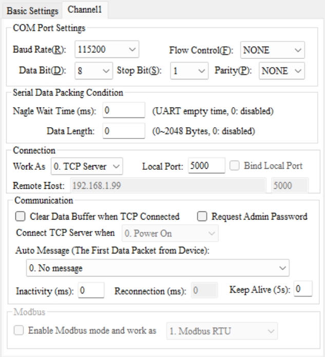 |
| Figure: Channel1 Settings |
COM Port Settings
-
Baud Rate - Displays/sets the serial port baud rate. The default is 115200. Users can select 16 common baud rates ranging from 1200 bps to 460800 bps.
-
Data Bit: Displays/sets the data bits of the serial port. The default is 8. It can be set to 7 or 8.
-
Parity: Displays/sets the parity bit of the serial port. The default is NONE. It can be set to NONE, ODD, or EVEN.
-
Stop Bit: Displays/sets the stop bits of the serial port. The default is 1. It can be set to 1 or 2.
-
Flow Control: Serial port flow control function configuration. The default is NONE. It can be set to NONE or CTS/RTS.
Serial Data Packing Condition
-
by Nagle Waiting Time (ms) - This option features a package that serial port input data into Ethernet packets by time interval. The default value is 0 (no packetization) and the maximum value is 60000 ms.
-
by Data Length (byte) - This option features a package that packages the serial port input data into an Ethernet package by length. The default value is 0 (no packetization) and the maximum value is 2048 bytes.
Connection
-
Work As - It comes with a List box to choose the socket operation mode of the module. It includes TCP Server, TCP Client and UDP mode. The default socket operation mode is TCP Server.
-
Local Port - Displays/sets the local port number. The default is 5000 and the range is from 0 to 65535.
-
Bind Local Port - Binds the local port number. When checked, it enables the function of binding the local port number. This is effective when the module runs in TCP Client mode.
-
Remote Host - Displays/sets the IP address/domain name of the remote host. The text box will be unlocked when the module is operating in TCP Client and UDP modes. The default is 192.168.1.99 and the text box is locked. If this is set to the remote host's domain name, the module will automatically perform domain name resolution. The maximum length of the domain name is 32 characters.
-
Remote Port - Displays/sets the port number of the remote host. The text box will be unlocked when the module is operating in TCP Client and UDP modes. The default is 5000 and the text box is locked. The range is 0 to 65535.
Note: Some protocols in the Ethernet protocol have default port numbers. These port numbers should be avoided. The default occupied port numbers can be found in the appendix.
Communication
-
Clean Data Buffer when TCP Connected - Whether to clear the serial port Buffer after connection establishment. This option will only be activated when it is enabled (checked) and the module is working in TCP modes. The default is disabled (unchecked).
-
Connect TCP Server when - In TCP client mode, the user could choose the priority for TCP client to connect to the Server. It can be set as "Power on" to establish the connection immediately after "power-on" or wait until "Serial data received" to establish the connection after receiving data from the serial port. The default is power-on and locked.
-
Request Admin Password - This feature is activates the connection verification password. It is effective when the device is operating in TCP Server mode. If the checkbox is checked, the client sends a connection request and establishes a connection in TCP Server mode, the client needs to send the device password to communicate with the module. Otherwise, the connection will be disconnected. The default is disabled (unchecked) and locked.
-
Auto Message - Sends information after connection establishment. It is effective in TCP mode. You can choose "No message" to not send information (default), "Send Device Name" to send the device name, "Send MAC Address" to send the device MAC address, or "Send IP Address" to send the device IP address.
-
Inactivity Time (ms) - Sets/Displays the time interval for timeout disconnection. This option is effective when the device is in TCP mode. The range of values is from 0 to 60000 in ms. The default value is 0 (this function is disabled).
-
TCP Reconnection Time (ms) - Sets/Displays the reconnection time. This option is effective when the device is in TCP Client mode. It sets the TCP Client's wait time before reconnecting to the TCP Server after the connection is disconnected. The default value is 0, which means immediate reconnection. The range of values is from 0 to 60000 in ms.
-
Keep Alive Time (5s) - TCP connection keep alive time. This option is effective when the device is in TCP mode. The range of values is from 0 to 65536 with units of 5s. The default value is 0 (this function is disabled).