EOE-55RPL
Overview
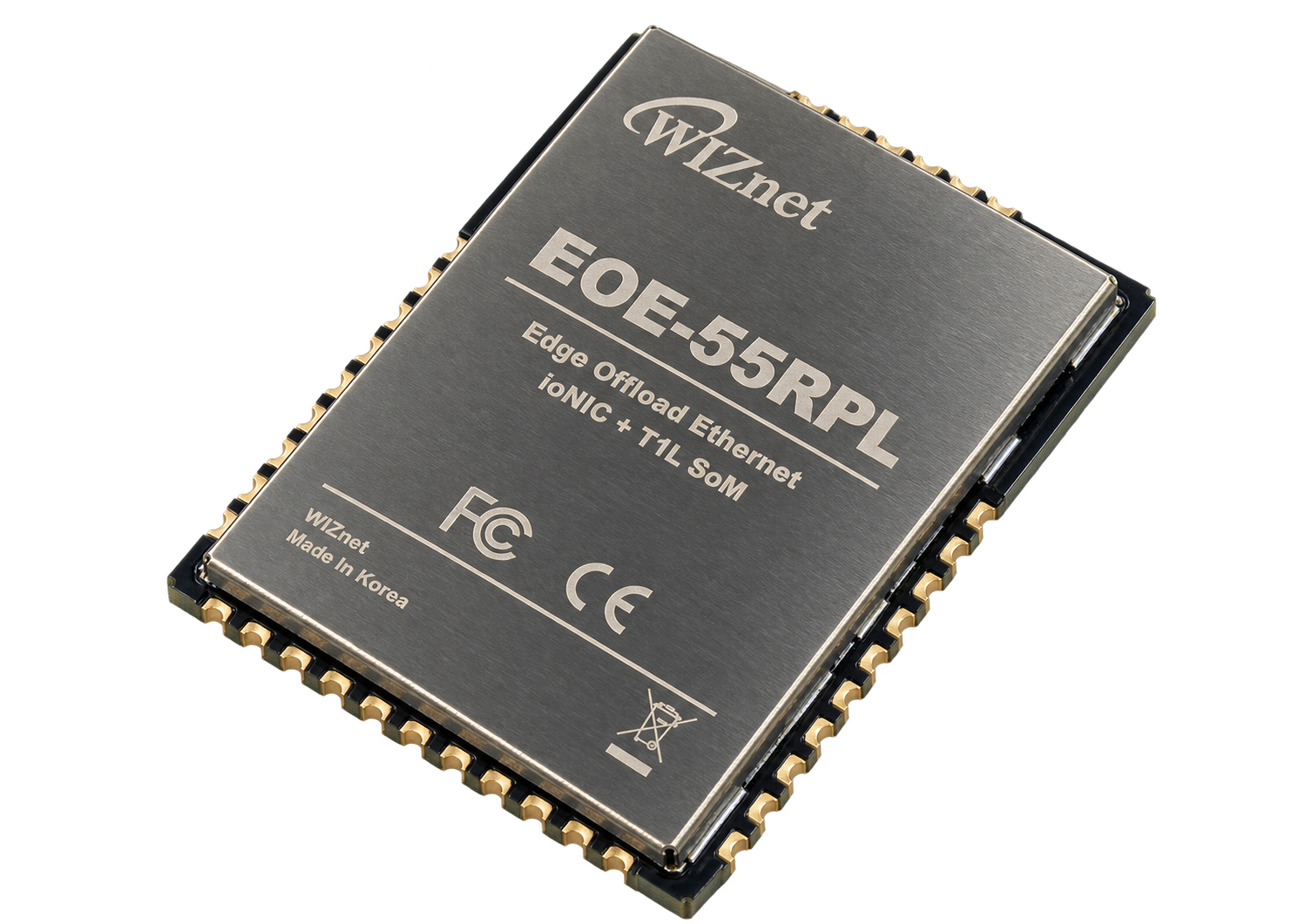
The EOE-55RPL is a compact Single Pair Ethernet (SPE) combo module that integrates the WIZnet W55RP20 with a 10/100BASE-TX to 10BASE-T1L media converter based on Analog Devices ADIN1200 and ADIN1100.
The W55RP20 combines a dual-core Arm Cortex-M0+ MCU with the W5500 Hardwired TCP/IP Ethernet Offload Engine, while the ADIN1200 and ADIN1100 provide the Ethernet media conversion between conventional 10/100BASE-TX Ethernet and 10BASE-T1L Single Pair Ethernet.
The EOE-55RPL is designed as a solder-down module for integration into a customer carrier board. It operates from a single 3.3 V supply and includes the required clock sources for both the W55RP20 and the 10BASE-T1L PHY.
Specifications
| Item | Specification |
|---|---|
| Type | 10/100BASE-TX to 10BASE-T1L Combo Module |
| Main device | W55RP20: dual-core Arm Cortex-M0+ MCU with integrated W5500 Hardwired TCP/IP engine and 2 MB flash |
| Media converter | Analog Devices ADIN1200 + ADIN1100 |
| SPE interface | 10BASE-T1L Single Pair Ethernet |
| TCP/IP protocols | TCP, UDP, ICMP, IPv4, ARP, IGMP, PPPoE |
| Host interface | UART or SPI, selectable by SPI_IF_SEL |
| Serial interfaces | Two TTL UART channels supporting RX, TX, RTS, CTS, DSR, and DTR when using S2E firmware |
| PHY management | MDC / MDIO interface internally connected to ADIN1100 and ADIN1200 |
| PHY management pins | MDC: GP27 / MDIO: GP28 |
| Debug | SWD (SWCLK, SWDIO) |
| USB | Native USB (D_P, D_N) exposed through the module interface |
| USB pins | D_P: Pin 26 / D_N: Pin 25 |
| On-module clocks | 12 MHz oscillator, 25 MHz crystal, and 50 MHz 10BASE-T1L PHY clock |
| Supply | Single 3.3 V supply |
| I/O voltage | 3.3 V; not 5 V tolerant |
| Operating temperature | −40 °C to +85 °C based on component ratings; module rating TBD |
| Dimensions | TBD |
| Module interface | Solder-down module; detailed pin assignment TBD |
10BASE-T1L Interface
The EOE-55RPL includes the required 10BASE-T1L MDI termination circuitry.
For stable operation and improved protection, the use of an external Common-Mode Choke (CMC) and appropriate protection components on the carrier board is recommended.
Refer to the EOE-55RPL evaluation board schematic for the recommended external MDI implementation.
Product Views
Interfaces
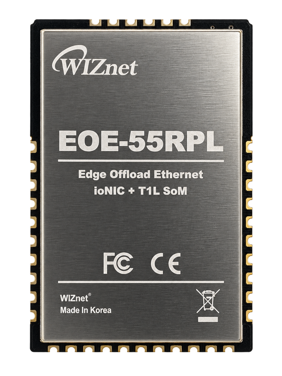
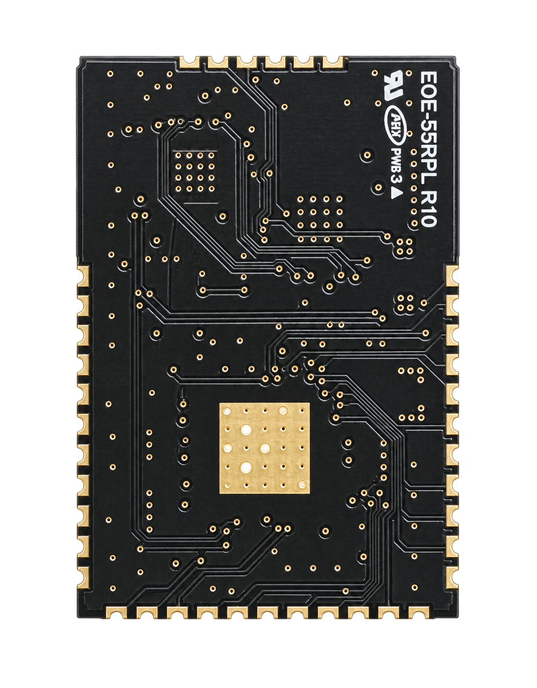
EOE-55RPL provides the following external interfaces for carrier-board integration:
- UART or SPI host interface
- Two UART channels when using S2E firmware
- Native USB interface for RP2040 BOOTSEL firmware upload
- SWD debug interface
- Reset and boot control signals
- 10BASE-T1L MDI interface
- Ethernet link and status outputs
The following PHY management signals are used internally and are not exposed through the module interface:
| Signal | Function | W55RP20 GPIO |
|---|---|---|
| MDC | ADIN1100 / ADIN1200 SMI management clock | GP27 |
| MDIO | ADIN1100 / ADIN1200 SMI management data | GP28 |
Control and Status Signals
Key control signals include:
RSTn— Active-low module resetRP_BOOT— RP2040 BOOTSEL controlFW_BOOT— S2E firmware boot controlFACT_RSTn— Factory resetHW_TRIG— AT command mode triggerDEBUG— Debug interfaceSPI_IF_SEL— Host interface selectionUART0_IF_SELUART1_IF_SEL
Ethernet status signals include:
LINKn— Ethernet link status, active lowLED_0— TBDLED_1— TBD
No indicator LEDs are mounted on the module. LEDs and appropriate current-limiting resistors should be implemented on the carrier board if visual status indication is required.
Firmware
The W55RP20 can be programmed through its native USB interface or SWD interface.
When the W55RP20 enters BOOTSEL mode by asserting RP_BOOT low during reset, firmware can be uploaded through the native USB D_P and D_N signals.
S2E (Serial-to-Ethernet) firmware may be used to provide UART-to-Ethernet functionality and associated control interfaces.
Documentation
| Document | Description |
|---|---|
| Datasheet (English) | Hardware specifications and module interfaces |
| 데이터시트 (한국어) | 하드웨어 사양 및 모듈 인터페이스 |
| Configuration Tool Guide | TBD |
Related Products
| Product | Description |
|---|---|
| EOE-55RPL-EVB | Evaluation board for EOE-55RPL |