Inter-Integrated Circuit (I2C)
Introduction
The I2C(Inter-Integrated Circuit) bus interface handles communications between the microcontroller and the serial I2C bus. It supports standard speed mode(100Kbps), Fast Mode(400Kbps).
Features
- Use APB interface
- Supports Slave and Master Mode
- Standard mode (up to 100 KHz)
- Fast mode (up to 400 KHz)
- Supports 7bit Slave address mode
- Start/Stop/Repeated Start detection
- Start/Stop/Repeated Start/Acknowledge generation
- Control the Read/Write operation
- General Call enable or disable
- Slave busy detection
- Repeated START
Functional description
I2C is comprised of both master and slave functions. For proper operation, the SDA and SCL pins must be configured as open-drain signals. A I2C bus configuration is shown below Figure.

In addition to receiving and transmitting data, this interface converts it from serial to parallel format and vice versa. The interrupt is enabled or disabled by software. The interface is connected to the I2C bus by a data pin (SDA) and by a Clock pin (SCL). It can be connected with a standard (up to 100 KHz), Fast mode (up to 400 KHz) I2C bus.
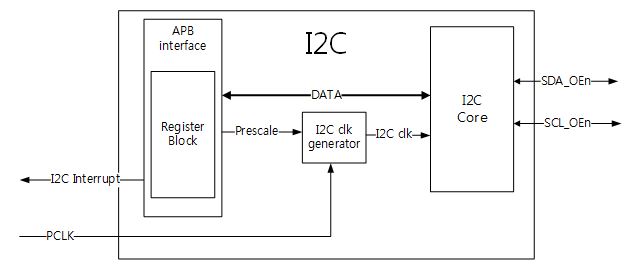
SDA is the bi- directions serial data line and SCL is the bi-directions serial clock line. The bus is considered idle when both lines are high. Every transaction on the I2C bus is nine bits long, consisting of eight data bits and a single acknowledge bit and data must be transferred MSB first.
###Data validity
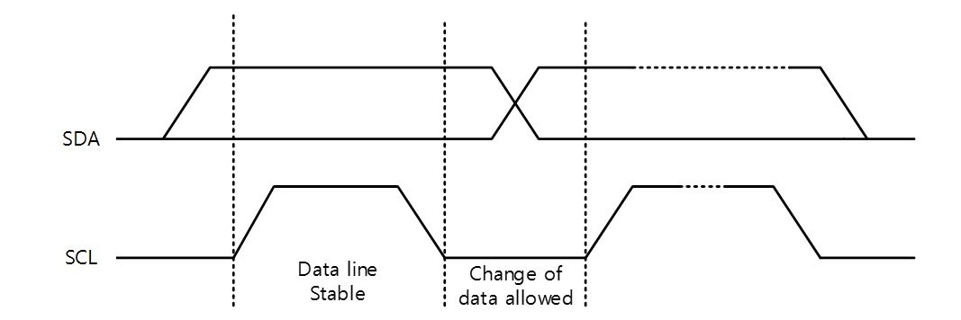
The data on the SDA line must be stable during the HIGH period of the SCL. The HIGH or LOW state of the data line can only change when the clock signal on the SCL line is LOW (The below Figure). One clock pulse is generated for each data bit transferred.
###Acknowledge
All bus transactions have a required acknowledge clock cycle that is generated by the master. During the acknowledge cycle, the transmitter cannot operate the next operation.
###Bit Command Controller
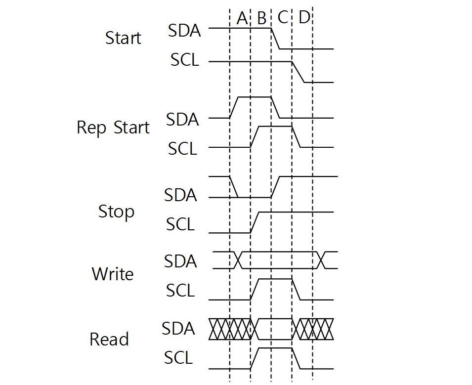
The Bit command Controller handles the actual transmission of data and the generation of the specific levels for START, STOP and Repeated START signals by controlling the SCL and SDA lines. The Byte Command controller tells the Bit command Controller which operation has to be performed. For a single byte read, the Bit command Controller receives 8 separate read command. Each bit-operation is divided into 5 pieces (idle and A,B,C,and D) except for a STOP operation which is divided into 4 pieces(idle and A, B,C)
####START and STOP Conditions
The protocol of the I2C bus defines two states to START and STOP conditions. A High to Low transition on the SDA line while SCL is High is one unique case and indicates a START condition. A Low to High transition on the SDA line while SCL is high defines a STOP condition.
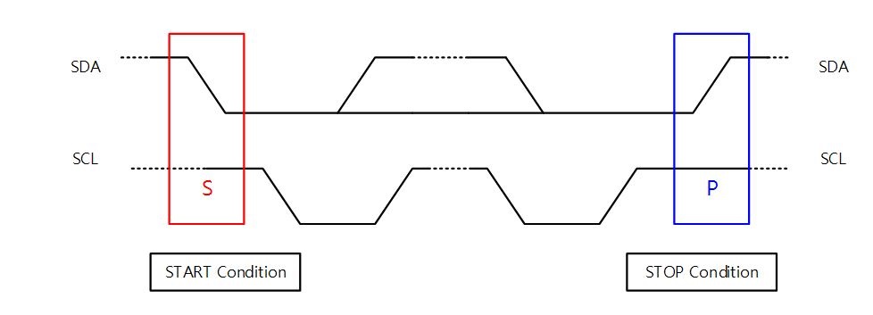
START and STOP conditions are always generated by the master. This bus is considered to be again a certain time after the STOP condition. The bus stays busy if a Repeated START is generated instead of a STOP condition.
####RESTART Condition

###Slave address
The SDA line must be eight bits long. Each byte must be followed by an Acknowledge bit.
![]https://github.com/Wiznet/img/products/w7500p/peripheral/i2c_7bit_slave_addr.jpg "Figure 7 7-bit Slave address")
###Read/Write bit
This address is seven bits followed by an eight bit which is a data direction bit(R/¯("W" )) : ‘0’ indicates a WRITE, ‘1’ indicates a READ There are two methods of setting data direction bit by I2Cx_CTR. The 32-bits I2Cx_CTR is reconfigured with COREEN, INTEREN, MODE, ADDR10, CTRRWN, CTREN. CTREN bit select the R/W – a ‘Zero’ indicates the slave address bit 0, a ‘one’ indicates a CTRRWN bit.
###Acknowledge(ACK) and Acknowledge(NACK)
The acknowledge bit takes place after every bytes. The acknowledge bit allows the receiver to signal the transmitter that the byte was successfully received and another byte may be sent. The master generates all clock pulses, including acknowledge ninth clock.
###Data transfer
The data transfer is managed through the shift, transmit data, and receive data registers. Data transfers follow the format shown in the below Figure. After START condition, a Slave address is transmitted. If CTREN bit in the I2Cx_CTR register is enable, LSB of Slave address (bit 0) is superseded by value of CTRRWN bit in the I2Cx_CTR register.
If CTREN bit in the I2Cx_CTR register is disable, LSB of slave address is used for Read/Write operation.
###Operating Modes
The interface can operate in one of four following:
- Master Transmitter Mode
- Master Receiver Mode
- Slave Transmitter Mode
- Slave Receiver Mode
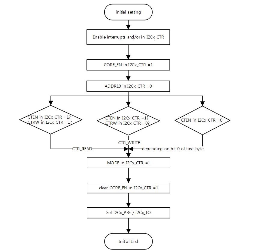
By default, it operates in slave mode. The interface switches from slave to master when it generates the mode bit in the I2Cx_CTR. And COREEN bit in the I2Cx_CTR must be switched from 1 to 0.
In Master mode
Master Transmitter Mode:
In this mode, data is transmitted from master to slave before the master transmitter mode can be entered and I2Cx_CTR must be initialized
Master Receiver Mode: In this mode, data is received from slave to master before the master receive mode can be entered and I2Cx_CTR must be initialized
In Slave mode
Slave Transmitter Mode:
In this mode, data is transmitted from slave to master and setting of I2Cx_SADDR must be done.
Slave Receiver Mode: In this mode, data is received from master to slave before the master transmitter mode can be entered and setting of I2Cx_SADDR must be done.
###Interrupts
The I2C can generate interrupt when the following conditions are observed:
- Start conditions on bus detected
- Stop conditions on bus detected
- Timeout error
- Master transaction completed
- Slave transaction received
I2C bus have separate interrupt signals.
Master mode
Initialization
The below figures that follow show the command sequences available for the I2C master.
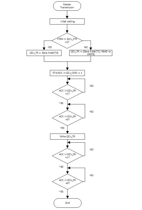
The below figure shows the master operation using a 7-bit slave address.
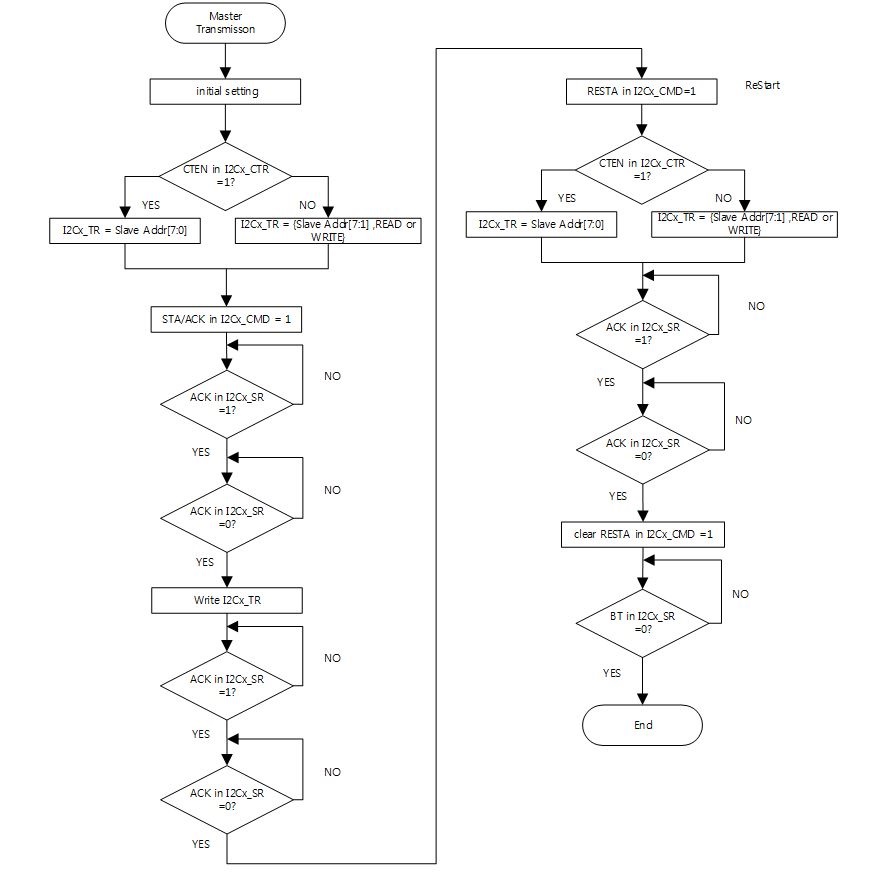
below Figure shows the operation of repeated START.
The repeated START operates for data read operation execution.
The operation sequences are Slave address, send data, repeated START, and send data.
Slave mode
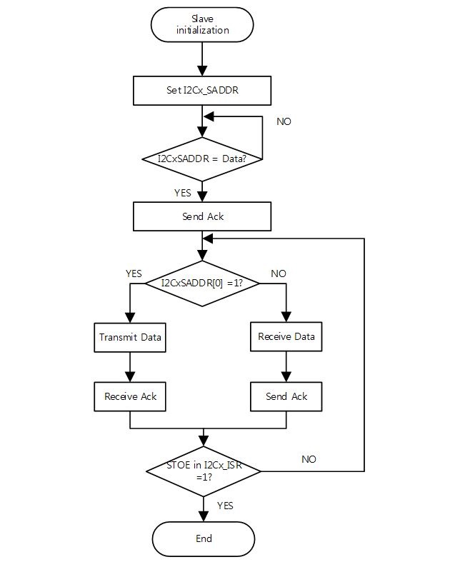
The below Figure shows the command sequences available for the I2C slave.
Peripheral_Examples
:!: When data read operation use,you have to use the repeat(restart condition). It use between write and read operation.