W5100S UDP Function
By setting some register and memory operation, W5100S provides internet connectivity. This chapter describes how it can be operated.
Initialization
Basic Setting
For the W5100S operation, select and utilize appropriate registers shown below.
- Mode Register (MR)
- Interrupt Mask Register (IMR)
- Retry Time-value Register (RTR)
- Retry Count Register (RCR)
For more information of above registers, refer to the “Register Descriptions.”
Setting network information
Basic network information setting for communication: It must be set the basic network information.
- SHAR(Source Hardware Address Register)
- It is prescribed that the source hardware addresses, which is set by SHAR, use unique hardware addresses (Ethernet MAC address) in the Ethernet MAC layer. The IEEE manages the MAC address allocation. The manufacturer which produces the network device allocates the MAC address to product.
- Details on MAC address allocation refer to the website as below.
- 🌎http://www.ieee.org/
- 🌎http://standards.ieee.org/regauth/oui/index.shtml
- GAR(Gateway Address Register)
- SUBR(Subnet Mask Register)
- SIPR(Source IP Address Register)
Set SOCKET memory information
This stage sets the socket TX/RX memory information. The base address and mask address of each SOCKET are fixed and saved in this stage.
In case of, assign 2Kbytes TX/RX memory per SOCKET
In case of, assign 2Kbytes TX/RX memory per SOCKET
{
Sn_RXMEM_SIZE(ch) = (uint8 *) 2; // Assign 2K rx memory per SOCKET
Sn_TXMEM_SIZE(ch) = (uint8 *) 2; // Assign 2K rx memory per SOCKET

/* Same method, set gS1_TX_BASE, gS1_TX_MASK, gS2_TX_BASE, gS2_TX_MASK,
gS3_TX_BASE, gS3_TX_MASK, gS4_TX_BASE, gS4_TX_MASK*/
}
Data Communications
After the initialization process, W5100S can transmit and receive the data with others by ‘open’ the SOCKET of TCP, UDP, IPRAW, and MACRAW mode. The W5100S supports the independently and simultaneously usable 4 SOCKETs. In this section, the communication method for each mode will be introduced.
UDP
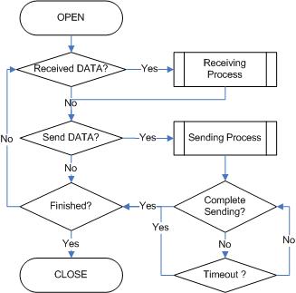
The UDP is a Connection-less protocol. It communicates without “connection SOCKET”. The TCP protocol guarantees reliable data communication, but the UDP protocol uses datagram communication which has no guarantees of data communication. Because the UDP does not use “connection SOCKET”, it can communicate with many other devices with the known host IP address and port number. This is a great advantage, communication with many others by using just one SOCKET. But also it has many problems such as loss of transmitted data, unwanted data received from others, etc. To avoid these problems and guarantee reliability, the host retransmits damaged data or ignores the unwanted data which is received from others. The UDP protocol supports unicast, broadcast, and multicast communication. It follows the below communication flow.
Unicast and Broadcast
The unicast is one method of UDP communication. It transmits data to one destination at one time. On the other hand, the broadcast communication transmits data to all receivable destinations by using ‘broadcast IP address (255.255.255.255)’. For example, suppose that the user transmits data to destination A, B, and C. The unicast communication transmits each destination A, B, and C at each time. At this time, the ARPTO can also occur when the user gets the destination hardware address of destinations A, B and C. User cannot transmit data to destinations which have ARPTO. The broadcast communication can simultaneously transmit data to destination A, B and C at one time by using “255.255.255.255” or “local address | (~subnet address)” IP address. At this time, there is no need to get the destination hardware address about destination A, B and C, and also ARPTOis not occurred.
Note: Broadcast IP
⇒ The Broadcast IP address can be obtained by performing a bit-wise
logical OR operation between the bit complement of the subnet mask and
the host’s IP address.
ex> If IP:”222.98.173.123” and the subnet mask:“255.255.255.0”,
broadcast IP is “222.98.173.255”
| Description | Decimal | Binary |
|---|---|---|
| HOST IP | 222.098.173.123 | 11011110.01100010.10101101.01111011 |
| Bit Complement Subnet mask | 000.000.000.255 | 00000000.00000000.00000000.11111111 |
| Bitwise OR | - | - |
| Broadcast IP | 222.098.173.255 | 11011110.01100010.10101101.11111111 |
SOCKET Initialization
For the UDP data communication, SOCKET initialization is required; it opens the SOCKET. The SOCKET open process is as followed. At first, choose one SOCKET among the 4 SOCKETS of W5100S, then set the protocol mode (Sn_MR(P3:P0)) of the chosen SOCKET and set the source port number Sn_PORT0 for communication. Finally, execute the OPEN command. After the OPEN command, the state of Sn_SR is changed to SOCK_UDP. Then the SOCKET initialization is complete.
{
START:
Sn_MR = 0x02; /* sets UDP mode */
Sn_PORT0 = source_port; /* sets source port number */
Sn_CR = OPEN; /* sets OPEN command */
/* wait until Sn_SR is changed to SOCK_UDP */
if (Sn_SR != SOCK_UDP) Sn_CR = CLOSE; goto START;
}
Check received data
Check the reception of UDP data from destination. User can also check for received data via TCP communication. It is strongly recommended to use the second method because of the same reasoning from TCP. Please refer to the “TCP SERVER” section. TCP SERVER
First method :
{
if (Sn_IR(RECV) == ‘1’) Sn_IR(RECV) = ‘1’; goto Receiving Process stage;
/* In this case, if the interrupt of Socket n is activated, interrupt occurs. Refer to IR, IMR
Sn_IMR and Sn_IR. */
}
Second Method :
{
if (Sn_RX_RSR0 != 0x0000) goto Receiving Process stage;
}
Receiving process
Process the received UDP data in Internal RX memory.
The structure of received UDP data is as below.
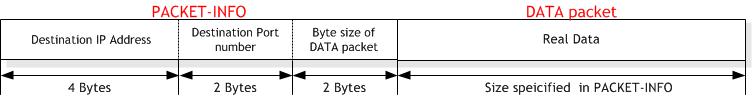
The received UDP data consists of 8bytes PACKET-INFO, and DATA packet. The PACKET-INFO contains transmitter’s information (IP address, Port number) and the length of DATA packet. The UDP can receive UDP data from many others. User can classify the transmitter by transmitter’s information of PACKET-INFO. It also receives broadcast SOCKET by using “255.255.255.255” IP address. So the host should ignore unwanted reception by analysis of transmitter’s information. If the DATA size of SOCKET n is larger than Internal RX memory free size, user cannot receive that DATA and also cannot receive fragmented DATA.
{
/* Get offset address */
src_ptr = Sn_RX_RD;
/* select RX memory, refer to RMSR(Rx Memory Size Register) */
cntl_byte = Socket_n_RX_Buffer
/* read head information (8 bytes) */
header_size = 8;
/* copy header_size bytes of get_start_address to header_address */
for(i=0; i<header_size; i++)
{
  header[i] = W5100S_READ(src_ptr, header);
}
/* update src_ptr */
src_ptr += header_size;

/* save remote peer information & received data size */
peer_ip = header[0 to 3];
peer_port = header[4 to 5];
get_size = header[6 to 7];

/* copy len bytes of src_ptr to destination_address */
for(i=0; i<get_size; i++)
{
  *(dst_ptr+i) = W5100S_READ(addr, cntl_byte, src_ptr+1);
}
/* increase Sn_RX_RD as length of len+ header_size */
Sn_RX_RD += get_size;
/* set RECV command */
Sn_CR = RECV;
}
Check send data / sending process
The size of DATA that the user wants to transmit cannot be larger than Internal TX memory. If it is larger than MTU, it is automatically divided by MTU unit and transmitted. The Sn_DIPR0 is set “255.255.255.255” when user wants to broadcast.
{
/* first, get the free TX memory size */
FREESIZE:
freesize = Sn_TX_FSR0;
if (freesize<len) goto FREESIZE; // len is send size

/* Write the value of remote_ip, remote_port to the Socket n Destination IP Address
Register(Sn_DIPR), Socket n Destination Port Register(Sn_DPORT). */
Sn_DIPR0 = remote_ip;
Sn_DPORT0 = remote_port;

/* Get offset address */
dst_ptr = Sn_TX_WR;
/* select TX memory, refer to TMSR(Tx Memory Size Register) */
cntl_byte = Socket_n_TX_Buffer
/* copy len bytes of source_address to dst_ptr */
for(i=0; i<len; i++)
{
  W5100S_WRITE(addr, cntl_byte, dst_ptr+i);
}
/* increase Sn_TX_WR0 as length of len */
Sn_TX_WR += len;
/* set SEND command */
Sn_CR = SEND;
}
Check complete sending / Timeout
To transmit the next data, user must check that the prior SEND command is completed. The larger the data size, the more time to complete the SEND command. Therefore, the user must properly divide the data to transmit. The ARPTO can occur when user transmits UDP data. If ARPTO occurs, the UDP data transmission has failed.
First method :
{
/* check SEND command completion */
while(Sn_IR(SENDOK)==‘0’) /* wait interrupt of SEND completion */
{
/* check ARPTO */
if (Sn_IR(TIMEOUT)==‘1’) Sn_IR(TIMEOUT)=‘1’; goto Next stage;
}
Sn_IR(SENDOK) = ‘1’; /* clear previous interrupt of SEND completion */
}
Second method :
{
If (Sn_CR == 0x00) transmission is completed.
If (Sn_IR(TIMEOUT bit) == ‘1’) goto next stage;
/* In this case, if the interrupt of Socket n is activated, interrupt occurs. Refer to
Interrupt Register(IR), Interrupt Mask Register (IMR) and Socket n Interrupt Register (Sn_IR).
*/
}
Check Finished / SOCKET close
If user doesn’t need the communication any more, close the SOCKET n.
{
/* clear remained interrupts */
Sn_IR = 0x00FF;
IR(n) = ‘1’;
/* set CLOSE command */
Sn_CR = CLOSE;
}
Multicast
The broadcast communication communicates with many and unspecified
others. But the multicast communication communicates with many specified
others who registered at a multicast-group. Suppose that A, B, and C are
registered at a specified multicast-group. If user transmits data to
multicast-group (contains A), B and C also receive the DATA for A. To
use multicast communication, the destination list registers to
multicast-group by using IGMP protocol. The multicast-group consists of
‘Group hardware address,’ ‘Group IP address,’ and ‘Group port number.’
User cannot change the ‘Group hardware address’ and ‘Group IP address.’
But the ‘Group port number’ can be changed.
The ‘Group hardware address’ is selected at the assigned range (From
“01:00:5e:00:00:00”to “01:00:5e:7f:ff:ff”) and the ‘Group IP address’
is selected in D-class IP address (From “224.0.0.0” to
“239.255.255.255”, please refer to the website;
🌎 http://www.iana.org/assignments/multicast-addresses).
When selecting, the upper 23bits of 6bytes ‘Group hardware address’ and
the 4bytes ‘Group IP address’ must be the same. For example, if the user
selects the ‘Group IP address’ to “244.1.1.11,” the ‘Group hardware
address’ is selected to “01:00:5e:01:01:0b.” Please refer to the
“RFC1112” (🌎 http://www.ietf.org/rfc.html).
In the W5100S, IGMP processing to register the multicast-group is
internally (automatically) processed. When the user opens the SOCKET n
with multicast mode, the “Join” message is internally transmitted. If
the user closes it, the “Leave” message is internally transmitted. After
the SOCKET opens, the “Report” message is periodically and internally
transmitted when the user communicates.
The W5100S support IGMP version 1 and version 2 only. If user wants use
an updated version, the host processes IGMP directly by using the IPRAW
mode SOCKET.
SOCKET Initialization
Choose one SOCKET for multicast communication among 4 SOCKETs of W5100S. Set the Sn_DHAR0 to ‘Multicast-group hardware address’ and set the Sn_DIPR0 to ‘Multicastgroup IP address.’ Then set the Sn_PORT0 and Sn_DPORT0 to ‘Multicast-group port number.’ Set the Sn_MR(P3:P0) to UDP and set the Sn_MR(MULTI) to ‘1.’ Finally, execute OPEN command. If the state of Sn_SR is changed to SOCK_UDP after the OPEN command, the SOCKET initialization is completed.
{
START:
/* set Multicast-Group information */
/* set Multicast-Group H/W address(01:00:5e:01:01:0b) */
Sn_DHAR[0:5] = {0x01,0x00,0x5e,0x01,0x01,0x0b};

/* set Multicast-Group IP address(211.1.1.11) */
Sn_DIPR[0:3] = {211,1,1,11};

Sn_DPORT[0:1] ={0x0B,0xB8}; /* set Multicast-GroupPort number(3000) */
Sn_PORT[0:1] = {0x0B,0xB8}; /* set SourcePort number(3000) */
Sn_MR = 0x02 | 0x80; /* set UDP mode & Multicast on Socket n Mode Register */
Sn_CR = OPEN; /* set OPEN command */
/* wait until Sn_SR is changed to SOCK_UDP */
if (Sn_SR != SOCK_UDP) Sn_CR = CLOSE; goto START;
}
Check received data
Refer to the “Unicast & Broadcast.” section.
Receiving process
Refer to the “Unicast & Broadcast.” section. Unicast & Broadcast
Check send data / Sending Process
Since the user sets the information about multicast-group at SOCKET initialization, user does not need to set IP address and port number for destination any more. Therefore, copy the transmission data to internal TX memory and executes SEND command.
{
/* first, get the free TX memory size */
FREESIZE:
freesize = Sn_TX_FSR;
if (freesize<len) goto FREESIZE; // len is send size
/* calculate offset address */
dst_mask = Sn_TX_WR0 &gSn_TX_MASK; // dst_mask is offset address
/* calculate start address(physical address) */
dst_ptr = gSn_TX_BASE + dst_mask; // dst_ptr is physical start address
/* if overflow SOCKETTX memory */
if ( (dst_mask + len) > (gSn_TX_MASK + 1) )
{
/* copy upper_size bytes of source_addr to destination_address */
upper_size = (gSn_TX_MASK + 1) ? dst_mask;
memcpy((0x0000 + source_addr), (0x0000 + dst_ptr), upper_size);
/* update source_addr*/
source_addr += upper_size;
/* copy left_size bytes of source_addr to gSn_TX_BASE */
left_size = len ? upper_size;
memcpy( source_addr, gSn_TX_BASE, left_size);
}
else
{
/* copy len bytes of source_addr to dst_ptr */
memcpy( source_addr, dst_ptr, len);
}
/* increase Sn_TX_WR as length of len */
Sn_TX_WR0 += send_size;
/* set SEND command */
Sn_CR = SEND;
}
Check complete sending / Timeout
Since the host manages all protocol process for data communication, timeout cannot occur.
{
/* check SEND command completion */
while(S0_IR(SENDOK)==‘0’); /* wait interrupt of SEND completion */
S0_IR(SENDOK) = ‘1’; /* clear previous interrupt of SEND completion */
}
Check finished / SOCKET close
Refer to the “Unicast & Broadcast.” section. Unicast & Broadcast