WIZPoE-S1
Overview
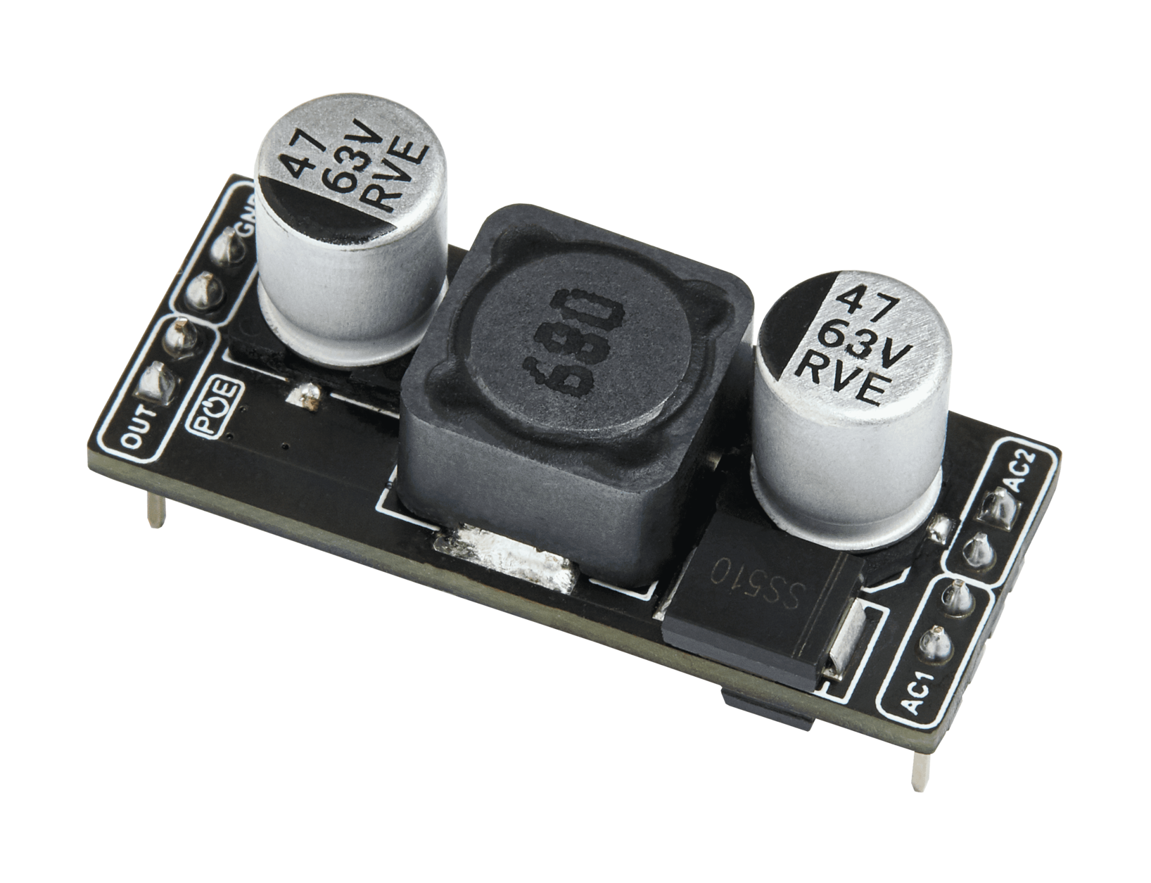
By using WIZPoE-S1, which supports both Mode A and Mode B, you can efficiently power external applications within the 8W range without the need for a power cable, not only for Ethernet but also for various external applications
Features
- IEEE802.3af compliant
- Mode A(Endspan), Mode B(Midspan)
- Wide input voltage range 40Vdc ~ 60Vdc
- High DC/DC conversion efficiency
- Non-Isolation
- Internal build in 2 channel bridge rectifiers
Compatible WIZnet Modules
| Standalone | Combined | MCU | Features | Dimension (mm) | |
|---|---|---|---|---|---|
| Surf 5 | 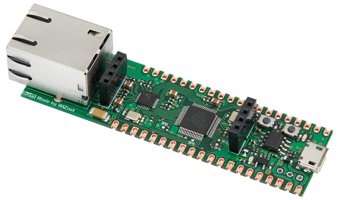 | 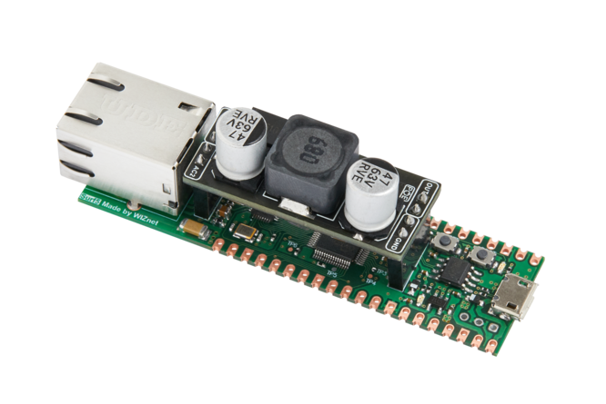 | W7500 | Compatible with the Raspberry Pi Pico Pinmap, Serial to Ethernet firmware provided, Offers various peripherals such as GPIO/SPI/PWM/ADC/DMA and more | 75mm x 21mm x 15mm |
| W55RP20-EVB-Pico | 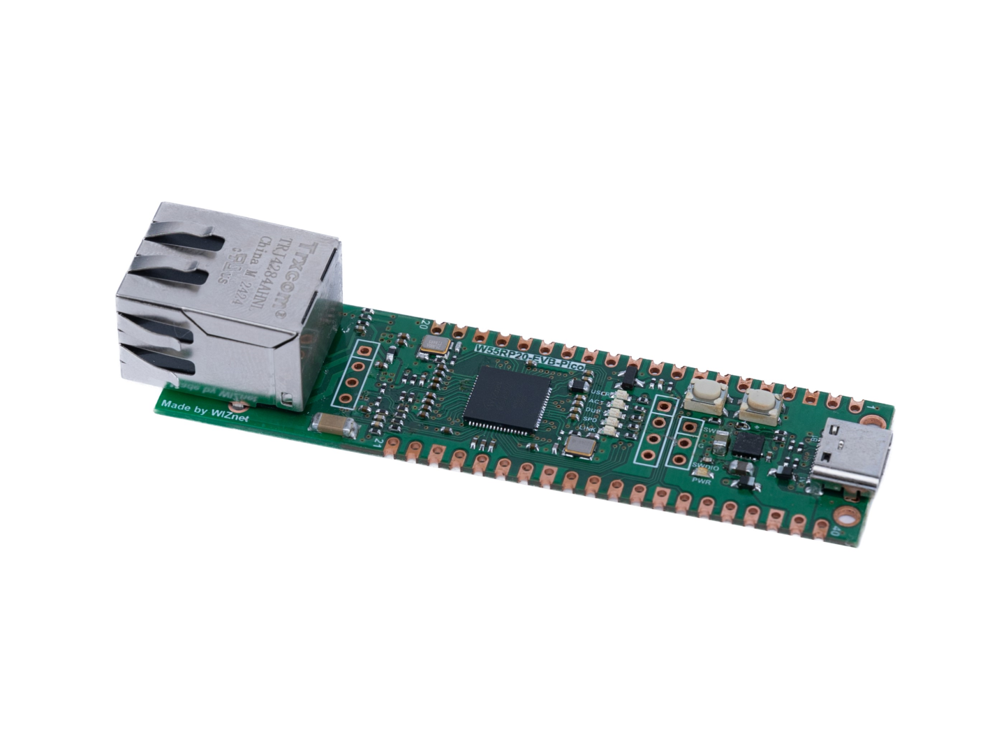 | To Be Updated Soon | W55RP20 | Compatible with the Raspberry Pi Pico Pinmap, Serial to Ethernet firmware provided, Offers various peripherals such as GPIO/SPI/PWM/ADC/DMA and more | 80mm x 21mm x 15mm |
| W5100S-EVB-Pico2 | 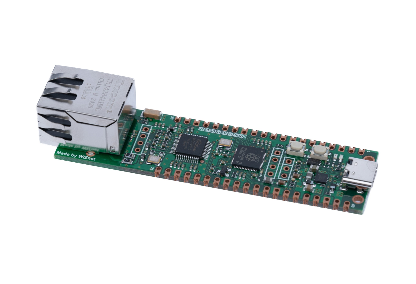 | To Be Updated Soon | RP2350 | Compatible with the Raspberry Pi Pico Pinmap, Serial to Ethernet firmware provided, Offers various peripherals such as GPIO/SPI/PWM/ADC/DMA and more | 80mm x 21mm x 15mm |
| W5500-EVB-Pico2 | 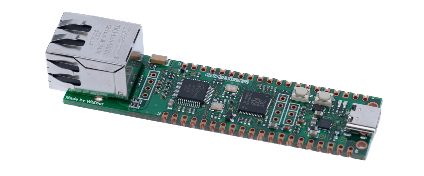 | To Be Updated Soon | RP2350 | Compatible with the Raspberry Pi Pico Pinmap, Serial to Ethernet firmware provided, Offers various peripherals such as GPIO/SPI/PWM/ADC/DMA and more | 80mm x 21mm x 15mm |
| W6100-EVB-Pico2 | 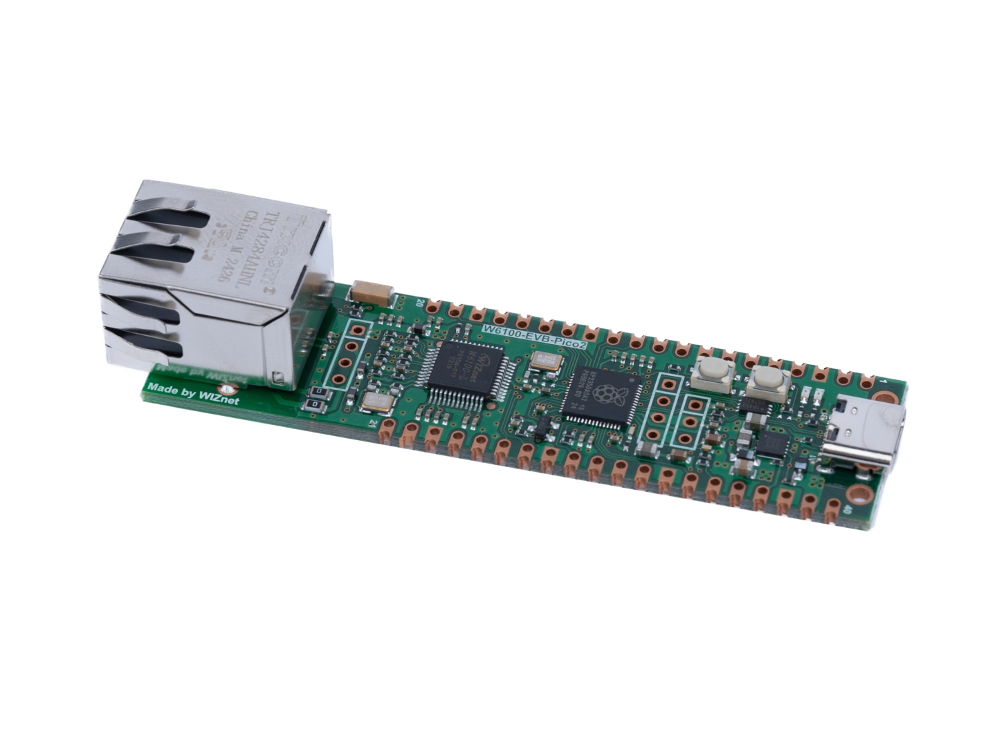 | To be Updated Soon | RP2350 | Compatible with the Raspberry Pi Pico Pinmap, Serial to Ethernet firmware provided, Offers various peripherals such as GPIO/SPI/PWM/ADC/DMA and more | 80mm x 21mm x 15mm |
Electrical Parameter technical standards
| No | Value | Symbol | Min | Typical | Max | Units |
|---|---|---|---|---|---|---|
| 1 | Input Voltage | VCC | 40 | 60 | V | |
| 2 | Output Voltage | VCC | 4.75 | 5 | 5.25 | V |
| 3 | Output Power | PWR | 8 | W | ||
| 4 | Switching Frequency | Freq | 280 | 300 | 320 | kHz |
Electrical Characteristics
| No | Value | Symbol | Min | Typical | Max | Units |
|---|---|---|---|---|---|---|
| 1 | Line Regulation | VLINE | 2.5 | 7.5 | % | |
| 2 | Load Regulation | VLOAD | 2.5 | 7.5 | V | |
| 3 | Output Ripple and Noise | VRN | 20 | 100 | 200 | mVp-p |
| 4 | Load Regulation | RLOAD | 150 | 200 | 250 | mA |
| 5 | Efficiency @80% Load | EFF | 70 | 80 | 90 | % |
Hardware Specification
Pin definition
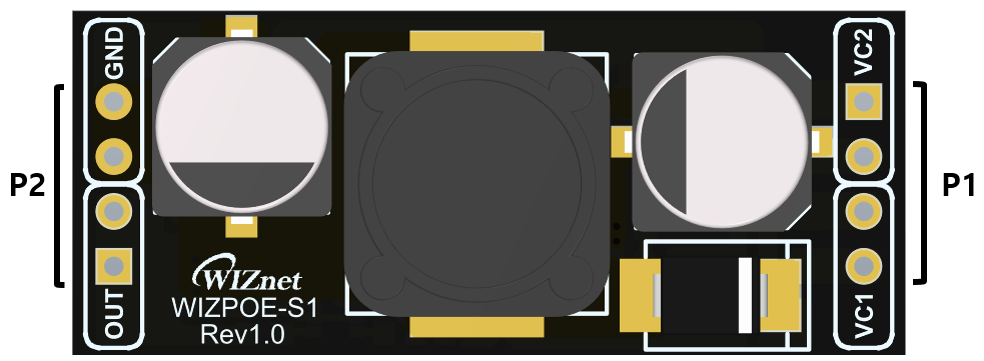
PoE Input - P1
| No | Value | Description |
|---|---|---|
| 1 | VC 1(+) | RX Input (1). This input pin is used in conjunction with VC1 (-) and connects to the center tap of the transformer connected to pins 1&2 of the RJ45 connector (RX) - it is not polarity sensitive. WIZPoE this pin is direct Input +. This pin connects to the positive (+) output of the input bridge rectifier. |
| 2 | VC 1(-) | TX Input (2). This input pin is used in conjunction with VC1 (+) and connects to the center tap of the transformer connected to pins 3&6 of the RJ45 connector (TX) - it is not polarity sensitive. WIZPoE this pin is direct Input -. This pin connects to the negative (-) output of the input bridge rectifier. |
| 3 | VC 2(+) | Direct Input (1). This input pin is used in conjunction with VC2 (-) and connects to pin 4 & 5 of the RJ45 connector - it is not polarity sensitive. WIZPoE this pin is direct Input +. This pin connects to the positive (+) output of the input bridge rectifier. |
| 4 | VC 2(-) | Direct Input (2). This input pin is used in conjunction with VC2 (-) and connects to pin 7 & 8 of the RJ45 connector - it is not polarity sensitive. WIZPoE this pin is direct Input -. This pin connects to the negative (-) output of the input bridge rectifier |
PoE Output - P2
| No | Value | Description |
|---|---|---|
| 1 | OUT | +5V Voltage Output |
| 2 | OUT | +5V Voltage Output |
| 3 | GND | Ground |
| 4 | GND | Ground |
Technical Reference
WIZPoE-S1 Datasheet
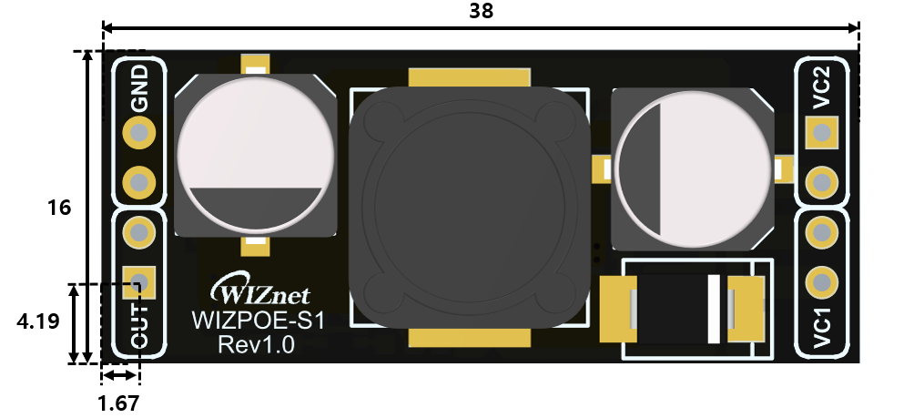
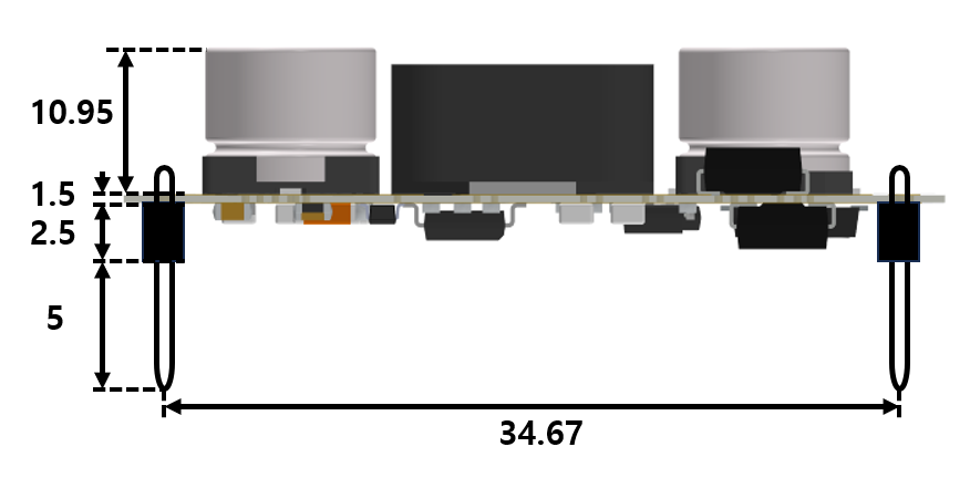
Dimension (Unit : mm)
Certification
EMI
-
RE (Radiated Emission)
| Date | Decription |
|---|---|
| NOV2023 | Only Test Report |
-
CE (Conducted Emission)
| Date | Decription |
|---|---|
| NOV2023 | Only Test Report |