Datasheet
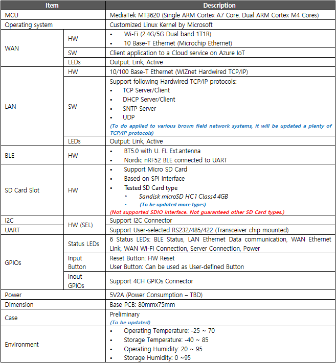
Specification
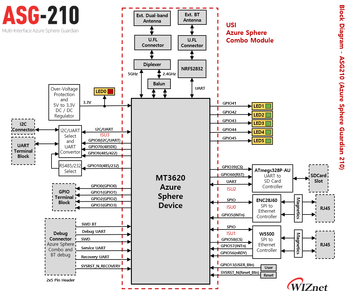
Block Diagram
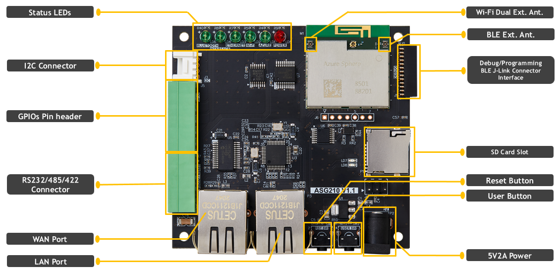
Callout
Pinout
Electrical Characteristics
Operating Conditions
| Symbol | Parameter | Min | Type | Max | Unit | |
|---|---|---|---|---|---|---|
| Vcc | Operating Voltage | 5 | V | |||
| Vss | Ground | 0 | V | |||
| VDDIO | Device supply votlage, I/O | Group 1 | 2.97 | 3.3 | 3.63 | V |
| VIH | Input High Voltage | |||||
| VIL | Input Low voltage | |||||
| VOH | Output High Voltage | |||||
| VOL | Output Low Voltage |
Hardware Function Description
USI Azure Sphere Combo module
Azure Sphere combo module is uniquely designed for IoT applications, with multi-functionality design-in support by standard SDK. Customers can easily migrate from discrete MCU solution.
Ethernet Interface
Public Network (ENC28J60)
The onboard MicroChip ENC28J60 ehternet controller device provides a 10 Mbps interface using TCP or UDP network protocols: • Public network, communicating with Azure IoT or other internet-based services
Use of Ethernet requires a “board configuration image” in addition to the user application image. This is required by the Azure Sphere Security Monitor to add Ethernet support to Azure Sphere OS. ISU0 is used for SPI0 interface signals to the ENC28J60 device, with interruptions on GPIO5.
| Signal Name | GPIO | Comments |
|---|---|---|
| SCK | GPIO47 | ISU0(SPI) |
| MOSI | GPIO46 | ISU0(SPI) |
| MISO | GPIO45 | ISU0(SPI) |
| CS | GPIO44 | ISU0(SPI) |
| INT | GPIO5 | Interrupt |
| RST_N | GPIO6 | Not Connected |
| SYSRST_N | SYSRST_N | Hardware System Reset |
More detail on this topic is available here: https://docs.microsoft.com/en-us/azure-sphere/network/connect-ethernet
Private Network (W5500)
The onboard W5500 chip is a Hardwired Internet controller designed as a full hardwired TCP/IP stack with WIZnet technology. It supports 10/100 Mbps interface using TCP or UDP network protocol:
• Private network, communicating with Brown-field various network protocol services
W5500 supports TCP, UDP, IPv4, ICMP, ARP, IGMP, and PPPoE and 8 independent SOCKETs are used simultaneously and 32KB internal memory for data communication. User can develop an Ethernet application easily by using the simple W5500 SOCKET program instead of handling a complex Ethernet controller. W5500 also provides WOL(Wake on LAN) and a Power Down Mode in order to reduce power consumption.
| Signal Name | GPIO | Comments |
|---|---|---|
| SCK | GPIO42 | ISU0(SPI) |
| MOSI | GPIO41 | ISU0(SPI) |
| MISO | GPIO40 | ISU0(SPI) |
| CS | GPIO39 | ISU0(SPI) |
| nRDY | GPIO56 | Ready to Read/Write |
| INT | GPIO57 | Interrupt |
| W5500_RESET | GPIO58 | W5500 Reset |
| SYSRST_N | SYSRST_N | Hardware System Reset |
More detail on this topic is available here: https://docs.wiznet.io/Product/iEthernet/W5500/overview
Dual Band Wi-Fi- Interface
The MT3620 on USI Azure Sphere Combo module integrates a Wi-Fi 802.11 bgn radio with on-board dual-band Ext. antenna connector. This is used to connect ASG210 to a wireless access point for Internet access.
BLE 5.0
USI Azure Sphere Combo module includes NRF52832 supports BLE 5.0 and antenna hole for external BT antenna. User can download and debug with BT SWD pin header on ASG Debugger board.
| Signal Name | GPIO | Comments |
|---|---|---|
| BT SWDIO | GPIO5 | Serial wire debug I/O for debug and programming |
| BT SWCLK | GPIO6 | Serial wire clock input for debug and programming |
| BT nRST | GPIO9 | Configurable as pin reset |
More detail on Application manifest is available here: https://docs.microsoft.com/en-us/samples/azure/azure-sphere-samples/wifi-setup-via-ble/
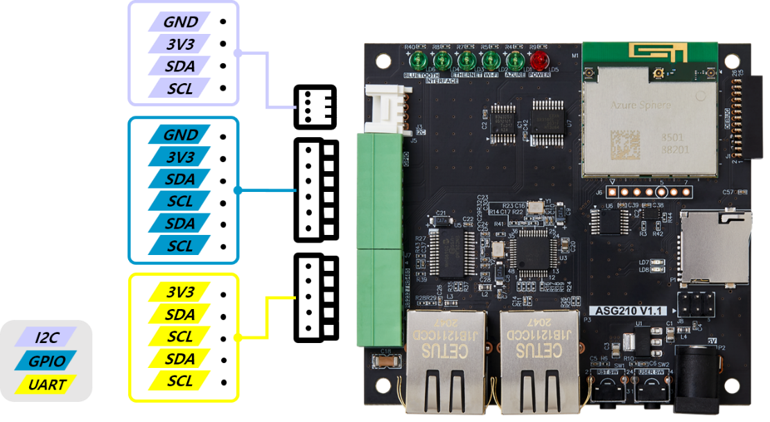
GPIO Terminal Block
ASG210 supports 4-GPIOs terminal block to communicate with external devices as Brown-field devices.
| Signal Name | GPIO | Comments |
|---|---|---|
| GPIO0 | GPIO0 | Digital Input/output port |
| GPIO1 | GPIO1 | Digital Input/output port |
| GPIO2 | GPIO2 | Digital Input/output port |
| GPIO3 | GPIO3 | Digital Input/output port |
UART Terminal Block (RS232/485/422)
ASG210 supports UART(RS232/485/422) terminal block to communicate with external devices as Brown-field devices. USI Azure Sphere Combo module supports ISU3 used as UART or I2C by user selection. To use ISU3 as UART, user should define UART Interface in Azure Sphere Application manifest file. And GPIO8(WIZNET_ASG210_ISU3_NSDA_RXD_SEL) should be “High Level” to select ISU3 RXD. ASG210 UART interface supports RS232/485/422 and user can select Serial communication type with GPIO9,10.
Ex1) RS485 selected by ‘Low Level’ GPIO10 and ‘High Level’ GPIO9. Ex2) RS232 selected by ‘High Level’ GPIO10.
| Signal Name | GPIO | Comments |
|---|---|---|
| S0 | GPIO8 | Select ‘High Level’ for ISU3 UART |
| 485/422 SEL | GPIO9 | Select ‘High Level’ for RS485 Select ‘Low Level’ for RS422 |
| 485/232 SEL | GPIO10 | Select ‘High Level’ for RS485/422 Select ‘Low Level’ for RS232 |
| SERIAL_TXD | GPIO66 | ISU3(UART) |
| RTS3 | GPIO67 | ISU3(UART) |
| RXD3 | GPIO68 | ISU3(UART) |
| SERIAL_CTS | GPIO69 | ISU3(UART) |
| Tx DE | GPIO70 | This signal is used only for RS485/422 Select ‘High Level’ for Tx Enable Select ‘Low Level’ for Tx Disable |
More detail on Application manifest is available here: https://docs.microsoft.com/ko-kr/azure-sphere/app-development/app-manifest
I2C Connector
ASG210 supports I2C connector to communicate with external devices such as Brown-field devices. USI Azure Sphere Combo module supports ISU3 used as I2C or UART by user selection. To use ISU3 as I2C, user should define I2C Interface in Azure Sphere Application manifest file, and GPIO8(WIZNET_ASG210_ISU3_NSDA_RXD_SEL) should be set to “Low Level” to select ISU3 SDA.
“Capabilities”:
{
“I2cMaster”: [“$WIZNET_ASG210_ISU3_NSDA_RXD_SEL”]
}
| Signal Name | GPIO | Comments |
|---|---|---|
| S0 | GPIO8 | Select ‘Low Level’ for ISU3 I2C |
| Null | GPIO66 | ISU3(I2C) |
| SCL | GPIO67 | ISU3(I2C) |
| SDA | GPIO68 | ISU3(I2C) |
| Null | GPIO69 | ISU3(I2C) |
| Null | GPIO70 | ISU3(I2C) |
More detail on Application manifest is available here: https://docs.microsoft.com/ko-kr/azure-sphere/app-development/app-manifest
SD Card Slot
ASG210 includes ATmega328P-AU, UART to SDCard, module running at 16MHz. It supports MicroSD card size from 64MB to 16GB. And the baud rate is configurable from 300bps to 1000000bps (the default baud rate is 9600 bps).
Verified SDCard class and size: • Sandisk microSDHC class4 4GB • Sandisk microSDHC 1 class4 8GB • Sandisk Ultra microSDHC 1 class10 16GB
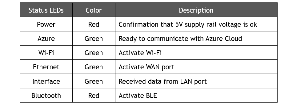
LED Status
An overview of ASG210 LED status as follows:
| Name | Status LEDs | Color | Description |
|---|---|---|---|
| LED0 | POWER | Red | Confirmation that 5V supply rail voltage is ok |
| LED1 | AZURE | Green | Ready to communicate with Azure Cloud |
| LED2 | Wi-Fi | Green | Activate Wi-Fi |
| LED3 | ETHERNET | Green | Activate WAN, ETH0 port |
| LED4 | INTERFACE | Green | Received data from LAN, ETH1 port |
| LED5 | BLUETOOTH | Green | Activate Blue-tooth |
System Architecture
System Architecture describes entire system which is ASG210 applied to Brown-field network and connected to Cloud Server and Management service
Block Diagram
ASG210 can send data via various interfaces to the cloud server and management service.
GPIOs, UART, I2C Operating System Block Diagram
In ASG210, M4 and A7 Cores of MT3620 can access to GPIOs, I2C, UART interface to communicate with user exsiting system, Brown field. ASG210 supports user-selected RS232/485/422 communication on mounted transceiver chip as well.
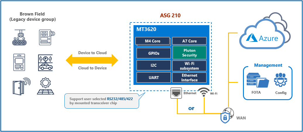
The received data from GPIOs/I2C/UART is sent to Azure cloud or management service on Azure Sphere security system via public network, Ethernet, or Wi-Fi. In the same manner, the exsiting system can receive data from Azure cloud or management service via Azure Sphere security system. It allows users to access the system remotely with guaranteed high-level security.
Dual Ethernet Operating System Block Diagram
In ASG200, M4 Core of MT3620 is connected to W5500, which is WIZnet’s hardwired TCP/IP chip with SPI interface. Since the hardwired TCP/IP stack is embedded in W5500, software TCP/IP stack is not required on the M4 Core for ethernet communication. M4 Core only receives data parsed by W5500 then sends it to A7 Core on inter-core communication. A7 Core secures this data on Azure Sphere security system and sends it Azure Cloud via public network.
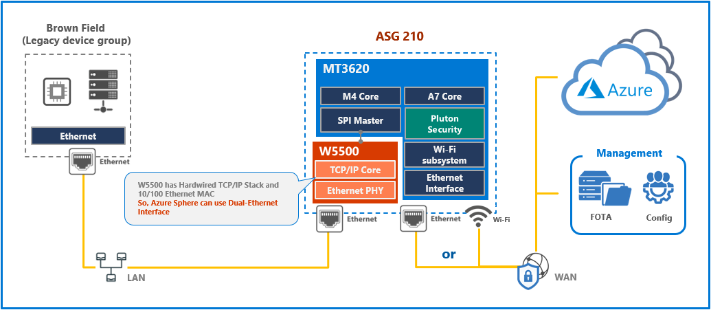
W5500 is only connected with the SPI interface to M4 Core. Hence, the data communication between the brownfield system and W5500 is out of Azure Sphere security system. However, W5500 can filter the ethernet packets used in data communication and allow reliable Ethernet communication even if heavy traffic occurs, such as a DDoS attack.
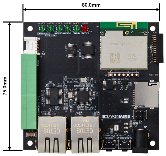
Dimensions
Base PCB
ASG210 Connections
An overview of how ASG210 interface to the equipment in local network is as follows:
- Power provided to ASG210 with 5V2A power adapter, power status LED turned on.
- For equipment with as Ethernet interface, connect Ethernet cable from ASG210’s LAN port to the equipment.
- Connect another Ethernet cable from ASG210’s WAN port to internet router for public network.
- Once connected, the LEDs on ASG210 should be as follows:
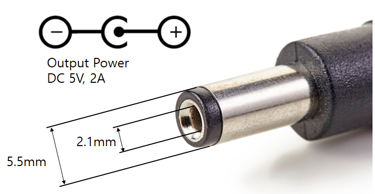
DC Power Cable Specification
Power to ASG210 is supplied directly via 5V2A DC connector or via the debugger board USB Micro B connector.