Dual Timer
Introduction
The dual timer consists two programmable 32-bit or 16-bit Free-running counters(FRCs) that can generate interrupts when they reach 0. There are two dual timers and 4 FRCs. One dual timers has one interrupt handler, resulting in two interrupts of timers. Also one dual timer has one clock but two clock enable signals. Users can select one repetition modes one-shot or wrapping mode, and wrapping mode consists free-running and periodic mode. Two FRCs are one set so two FRCs has one clock, reset, and interrupt but each FRC has an individual clock enable.
Features
- One dual timer has two Free-Running Counters(FRCs).
- One dual timer has one interrupt handler and one clock.
- One dual timer has two clock enable signals.
- There are 2 dual timers.
- A 32-bit or a 16-bit down counter.
- One of the following repetition modes: one-shot and wrapping mode.
- One of the following wrapping modes: Free-running and periodic mode.
- There is prescaler that can divide down the clock rate by 1, 16, or 256.
Functional description
Clock and clock enable
The dual timers contain PCLK and TIMERCLK clock inputs. PCLK is the main APB system clock and is used by the register interface. TIMERCLK is the input to the prescale units and the decrementing counters. PCLK and TIMERCLK are synchronous.
The dual timers consist two programmable 32-bit Free-Running Counters(FRC) which operate independently. The two timers operate from one TIMERCLK but Each FRC is controlled independently by individual clock enable.
Timer size
User can select FRC as 16-bit or 32-bit by using control register.
Prescaler
The timer has a prescaler that can divide down the enabled clock rate by 1, 16 or 256.
Repetition mode
There are two repetition mode: one-shot and wrapping mode.
Wrapping mode has two mode: free-running and periodic mode.
One-shot mode
The counter generates an interrupt once. When the counter reaches 0, it halts until users reprogram it. Users can do this as below:
- Clear the one-shot count bit in the control register, in which case the count proceeds according to the selection of wrapping mode(free-running or periodic mode).
- Writing a new value to the Load Value register.
Wrapping mode
Free-running mode
The counter wraps after reaching its zero value, and continues to count down from the maximum value. This is the default mode.
Periodic mode
The counter generates an interrupt at a constant interval, reloading the original value after wrapping past zero.
Interrupt
An interrupt is generated when the counter reaches 0 and is only cleared when the interrupt clear register is accessed.
The register holds the value until the interrupt is cleared.
Users can mask interrupts by writing 0 to the Interrupt Enable bit in the control register.
Users can read the following from status registers:
- Raw interrupt status before masking.
- Final interrupt status after masking.
The interrupts from the individual timers after masking are logically ORed into a combined interrupt.
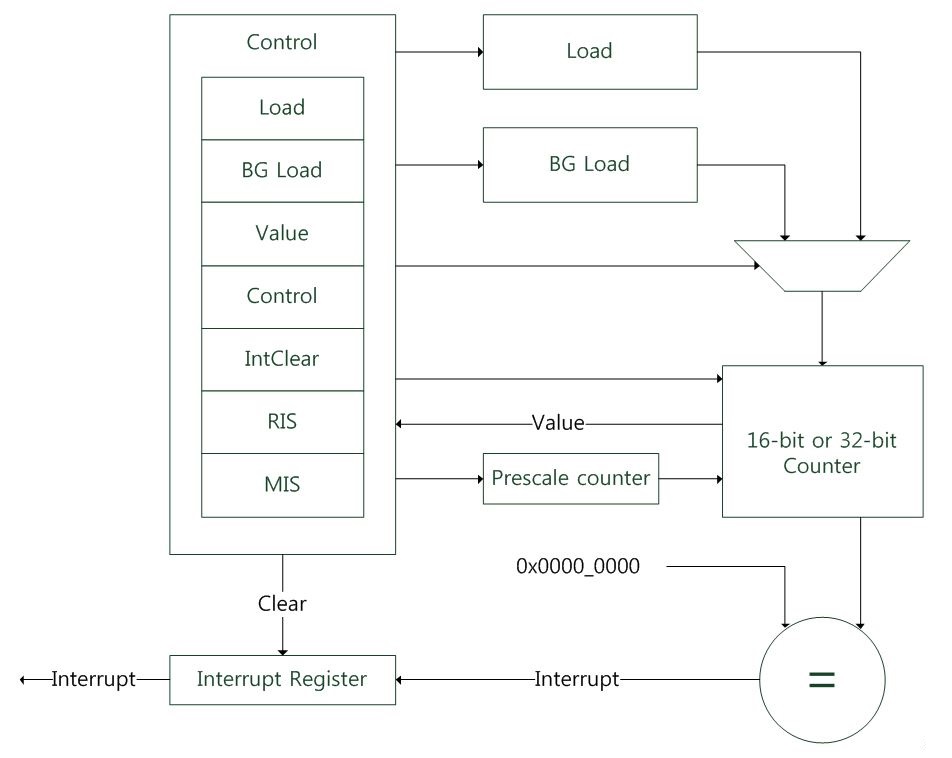
Operation
The operation of each timer is identical. The timer is loaded by writing to the load register and counts down to 0 if enabled. When a counter is already running, writing to the load register causes the counter to immediately restart at the new value. Writing to the background load value has no effect on the current count. In periodic mode, the counter continues to decrease to 0 and restart from the new load value.
An interrupt is generated when 0 is reached. Users can clear the interrupt by writing to the clear register. If users select one-shot mode, the counter halts when it reaches 0 until users deselect one-shot mode or write a new load value.
Otherwise, after reaching a zero count, if the timer is operating in free-running mode, it continues to decrease from its maximum value. If users select periodic mode, the timer reloads the count value from the load register and continues to decrease. In this mode, the counter effectively generates a periodic interrupt.
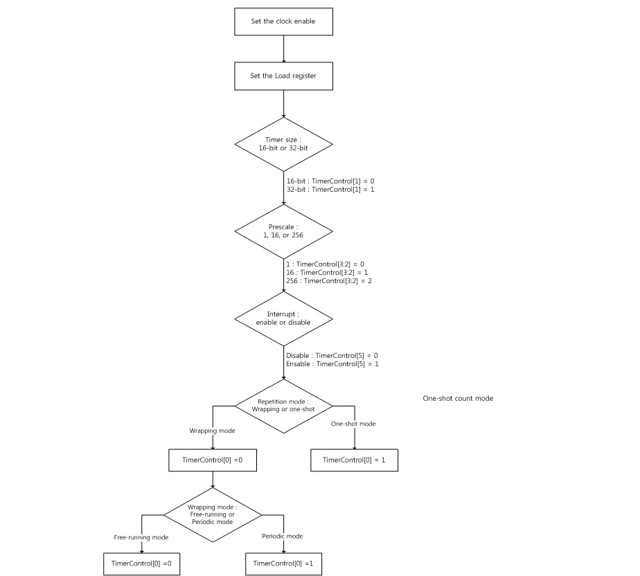
How to set the dual timers